SKU: OT5003 Numéro d’article: AA119 EAN: 8720618231512

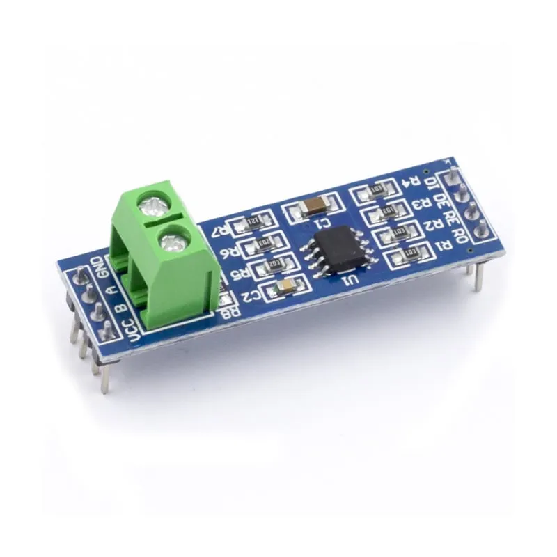
Module MAX485 avec la puce MAX485 à faible consommation pour la communication RS-485. Le RS485 est utilisé pour la communication série sur des distances plus longues que le RS232 direct ou le TTL et prend en charge plusieurs unités sur le même bus.
Spécifications du module MAX485 :
– Fonctionne sur : 5V.
– Connexion embarquée pour les fils RS-485.
– Dimensions : 44mm x 14mm.
Dimensions
Longueur : 4,39cm
Largeur : 1,41cm
Hauteur : 1,89cm
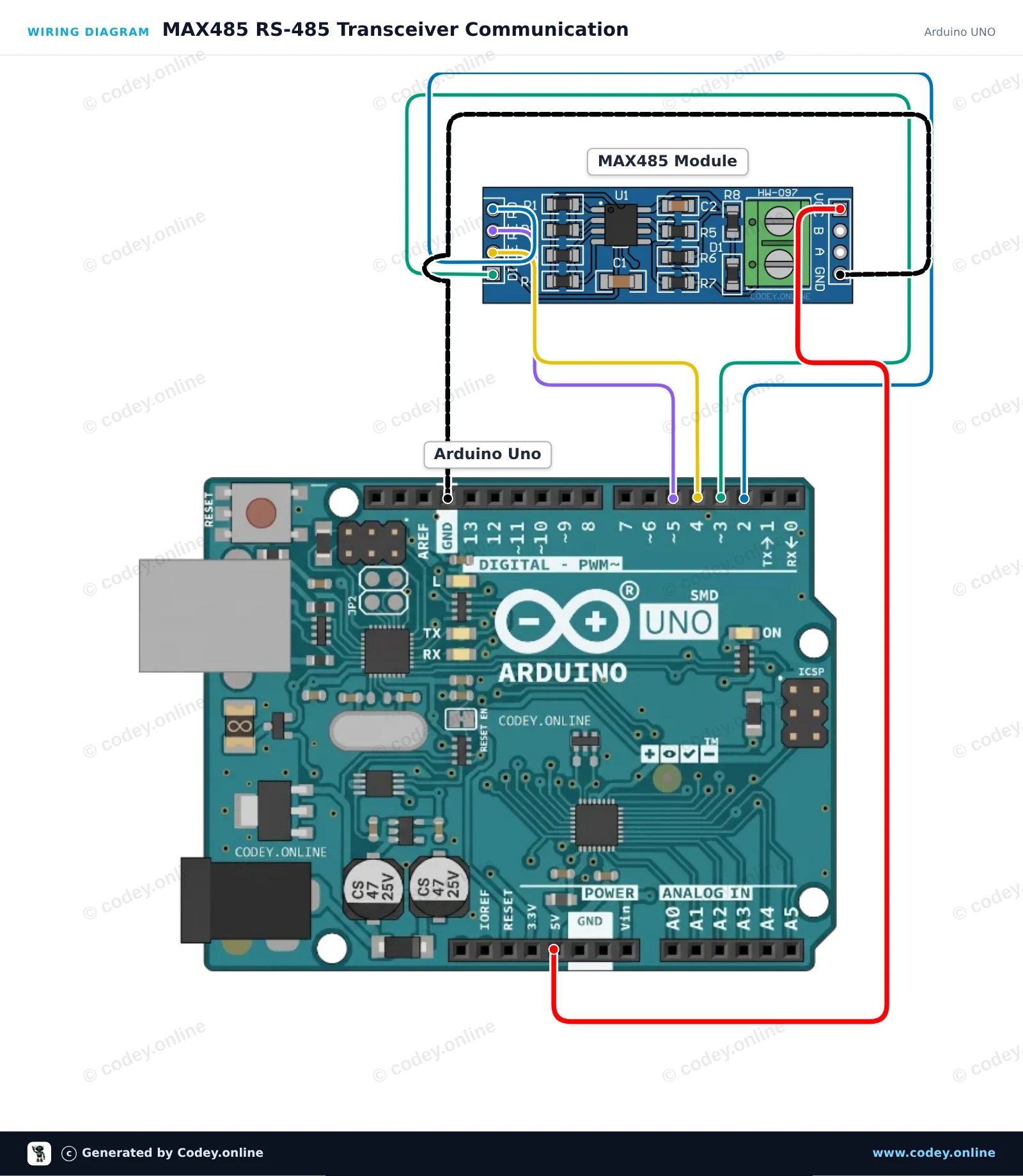
Voici comment connecter le Module convertisseur MAX485 TTL vers RS485 à un Arduino UNO ou à un ESP32, avec un exemple de sketch que tu peux téléverser directement.
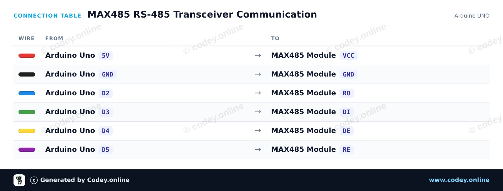
Ce circuit relie un Arduino Uno à un bus différentiel RS-485 à l’aide du transceiver MAX485. SoftwareSerial gère la communication avec le module, tandis que des broches numériques contrôlent les modes émission et réception. Tout message saisi dans le Serial Monitor est transmis via RS-485, et les données reçues sur le bus sont affichées à l’écran.
/*
 * ==================================================================
 *  Generated by Codey.online  —  https://www.codey.online
 * ==================================================================
 *  Project   : MAX485 RS-485 Transceiver Communication
 *  Board     : Arduino UNO (arduino:avr:uno)
 *  Parts     : MAX485 TTL to RS485 Converter Module
 *  Libraries : none (built-in)
 *
 *  Codey Online is an AI-powered browser IDE for Arduino and ESP32.
 *  Describe your project and Codey writes the code, draws the wiring
 *  diagram and uploads it to your board, straight from the browser.
 *  This code is free to use, modify and share, without warranty.
 * ==================================================================
 */

#include <SoftwareSerial.h>

const byte PIN_RO = 2;   // Receiver Out (RX)
const byte PIN_DI = 3;   // Driver In (TX)
const byte PIN_DE = 4;   // Driver Enable (Active HIGH)
const byte PIN_RE = 5;   // Receiver Enable (Active LOW)

SoftwareSerial rs485(PIN_RO, PIN_DI);

unsigned long lastSend = 0;
int packetCount = 0;

void setTransmitMode() {
  digitalWrite(PIN_RE, HIGH); // Disable receiver
  digitalWrite(PIN_DE, HIGH); // Enable driver
  delayMicroseconds(50);
}

void setReceiveMode() {
  digitalWrite(PIN_DE, LOW);  // Disable driver
  digitalWrite(PIN_RE, LOW);  // Enable receiver
  delayMicroseconds(50);
}

void rs485Send(const String &msg) {
  setTransmitMode();
  rs485.println(msg);
  rs485.flush();
  setReceiveMode();
}

void setup() {
  pinMode(PIN_DE, OUTPUT);
  pinMode(PIN_RE, OUTPUT);
  setReceiveMode();

  Serial.begin(115200);
  rs485.begin(9600);

  Serial.println(F("MAX485 RS-485 Transceiver Demo"));
  Serial.println(F("Type a message and press Enter to send over RS-485."));
}

void loop() {
  // Forward incoming Serial Monitor input to RS-485
  if (Serial.available()) {
    String input = Serial.readStringUntil('\n');
    input.trim();
    if (input.length() > 0) {
      Serial.print(F("Sending: "));
      Serial.println(input);
      rs485Send(input);
    }
  }

  // Forward received RS-485 data to Serial Monitor
  if (rs485.available()) {
    Serial.print(F("Received: "));
    while (rs485.available()) {
      char c = (char)rs485.read();
      Serial.print(c);
      delay(2);
    }
    Serial.println();
  }

  // Automatically send a heartbeat packet every 5 seconds
  if (millis() - lastSend >= 5000) {
    lastSend = millis();
    packetCount++;
    String packet = "Ping #" + String(packetCount);
    Serial.print(F("Auto-transmitting: "));
    Serial.println(packet);
    rs485Send(packet);
  }
}Wiring diagram and example code generated by Codey.online — https://www.codey.online
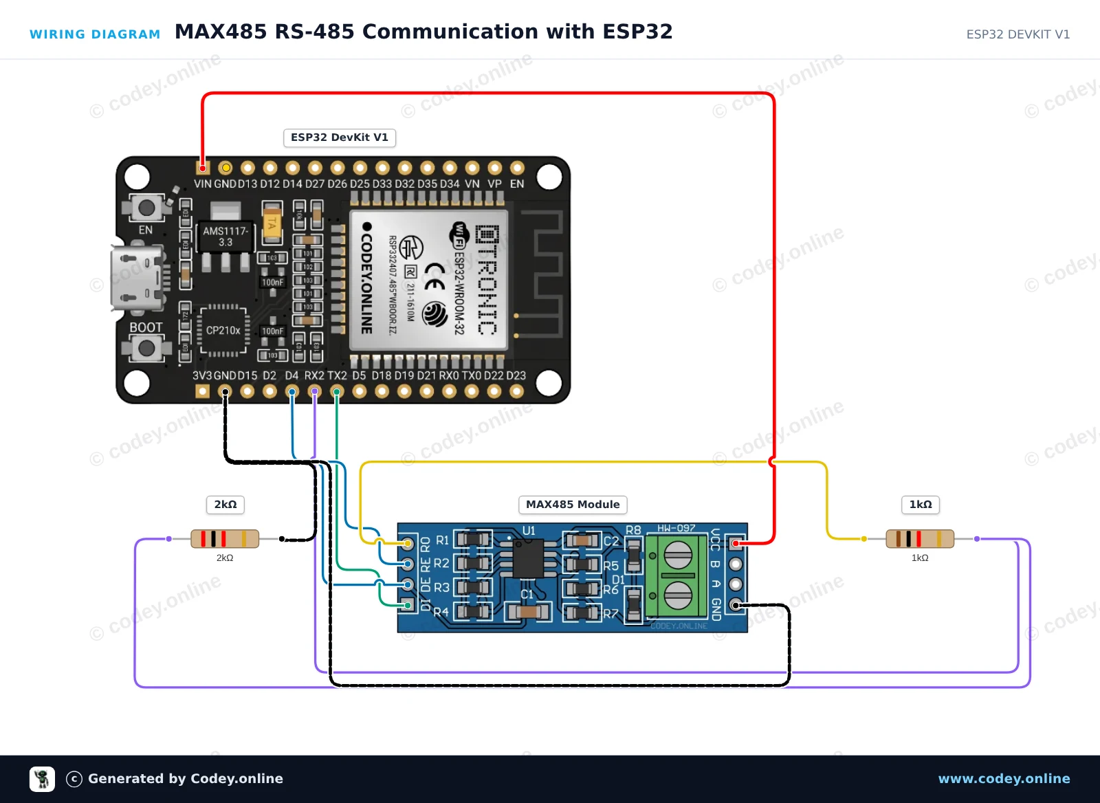
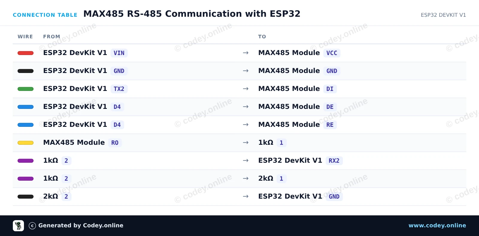
Ce projet montre comment envoyer et recevoir des données sur un bus RS-485 à l'aide du module MAX485 et de l'UART2 de l'ESP32. L'ESP32 met les broches DE/RE à HIGH pour transmettre un message heartbeat périodique et les met à LOW pour écouter les paquets RS-485 entrants. Un simple diviseur de tension 1kΩ/2kΩ abaisse en toute sécurité la sortie TTL 5V (RO) du module à 3.3V pour la broche RX de l'ESP32.
/*
 * ==================================================================
 *  Generated by Codey.online  —  https://www.codey.online
 * ==================================================================
 *  Project   : MAX485 RS-485 Communication with ESP32
 *  Board     : ESP32 DEVKIT V1 (esp32:esp32:esp32doit-devkit-v1)
 *  Parts     : MAX485 TTL to RS485 Converter Module
 *  Libraries : none (built-in)
 *
 *  Codey Online is an AI-powered browser IDE for Arduino and ESP32.
 *  Describe your project and Codey writes the code, draws the wiring
 *  diagram and uploads it to your board, straight from the browser.
 *  This code is free to use, modify and share, without warranty.
 * ==================================================================
 */

// MAX485 TTL to RS-485 transceiver demo with ESP32

const int CONTROL_PIN = 4; // Controls DE and RE (HIGH = Transmit, LOW = Receive)
const int RXD2_PIN = 16;
const int TXD2_PIN = 17;

unsigned long lastSendTime = 0;
int messageCount = 0;

void setup() {
  Serial.begin(115200);
  pinMode(CONTROL_PIN, OUTPUT);
  digitalWrite(CONTROL_PIN, LOW); // Start in receive mode

  // Initialize UART2 for RS-485 communication
  Serial2.begin(9600, SERIAL_8N1, RXD2_PIN, TXD2_PIN);

  Serial.println("RS-485 Transceiver Ready");
}

void loop() {
  // Send a message every 2 seconds
  if (millis() - lastSendTime >= 2000) {
    lastSendTime = millis();
    messageCount++;

    // Enable RS-485 transmitter
    digitalWrite(CONTROL_PIN, HIGH);
    delay(10);

    String msg = "Hello from ESP32 #" + String(messageCount);
    Serial2.println(msg);
    Serial2.flush(); // Wait until all outgoing bytes are transmitted

    // Return to receive mode
    digitalWrite(CONTROL_PIN, LOW);

    Serial.print("Sent over RS-485: ");
    Serial.println(msg);
  }

  // Check for incoming RS-485 data
  if (Serial2.available()) {
    Serial.print("Received via RS-485: ");
    while (Serial2.available()) {
      char c = (char)Serial2.read();
      Serial.print(c);
    }
    Serial.println();
  }
}Wiring diagram and example code generated by Codey.online — https://www.codey.online






 English
  Nederlands
  Deutsch
  Italiano
  Español
  Suomi
Suomi  Polski
  Dansk
Dansk  Ελληνικά
  Български
  Čeština
  Hrvatski
  Aileen