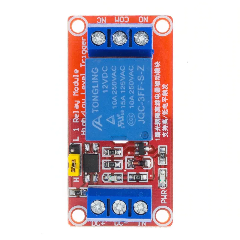
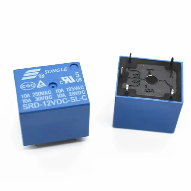
SKU: OT901-C111 Numéro d’article: BA050 EAN: 5408955714471

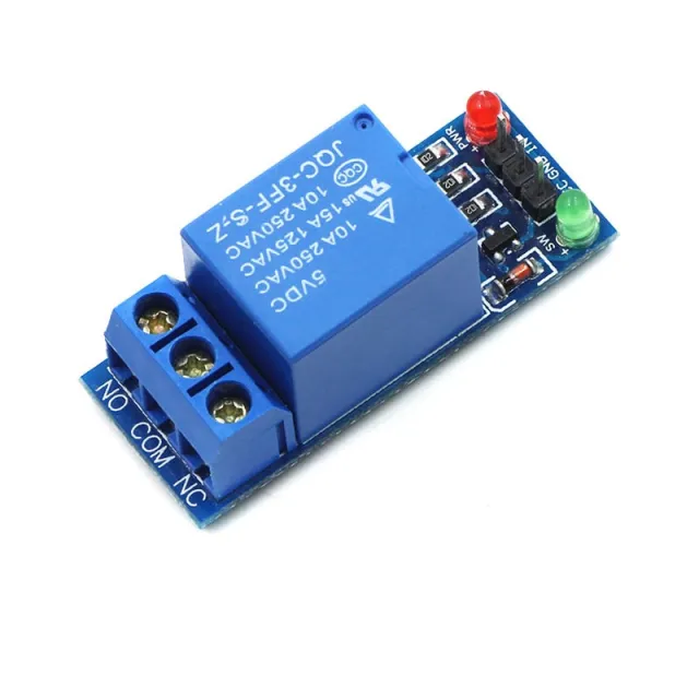
Mots-clés : relais 12v, relais 12v, relay 12v, 12v relay
Dimensions
Longueur : 5,1cm
Largeur : 2,54cm
Hauteur : 1,9cm
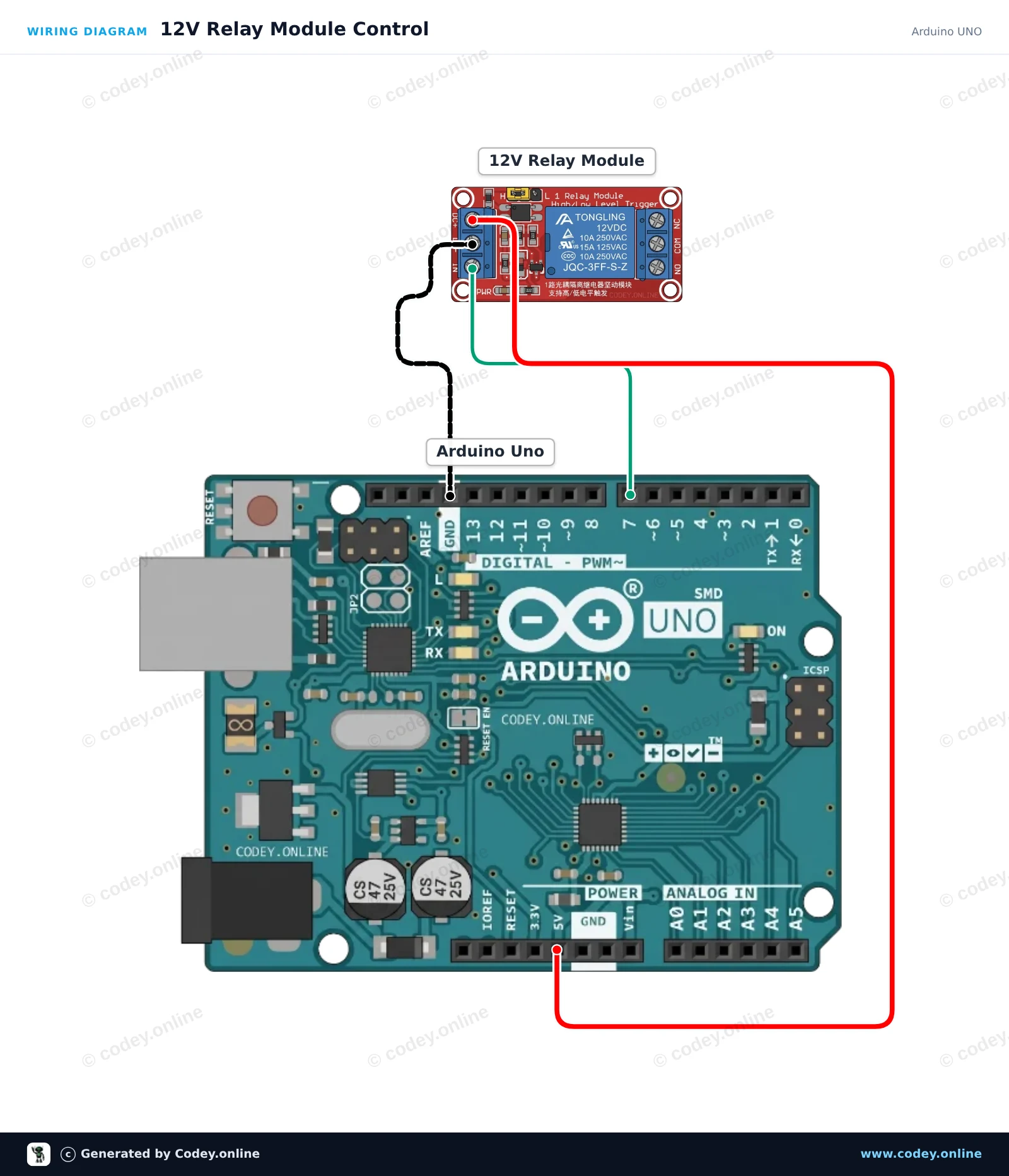
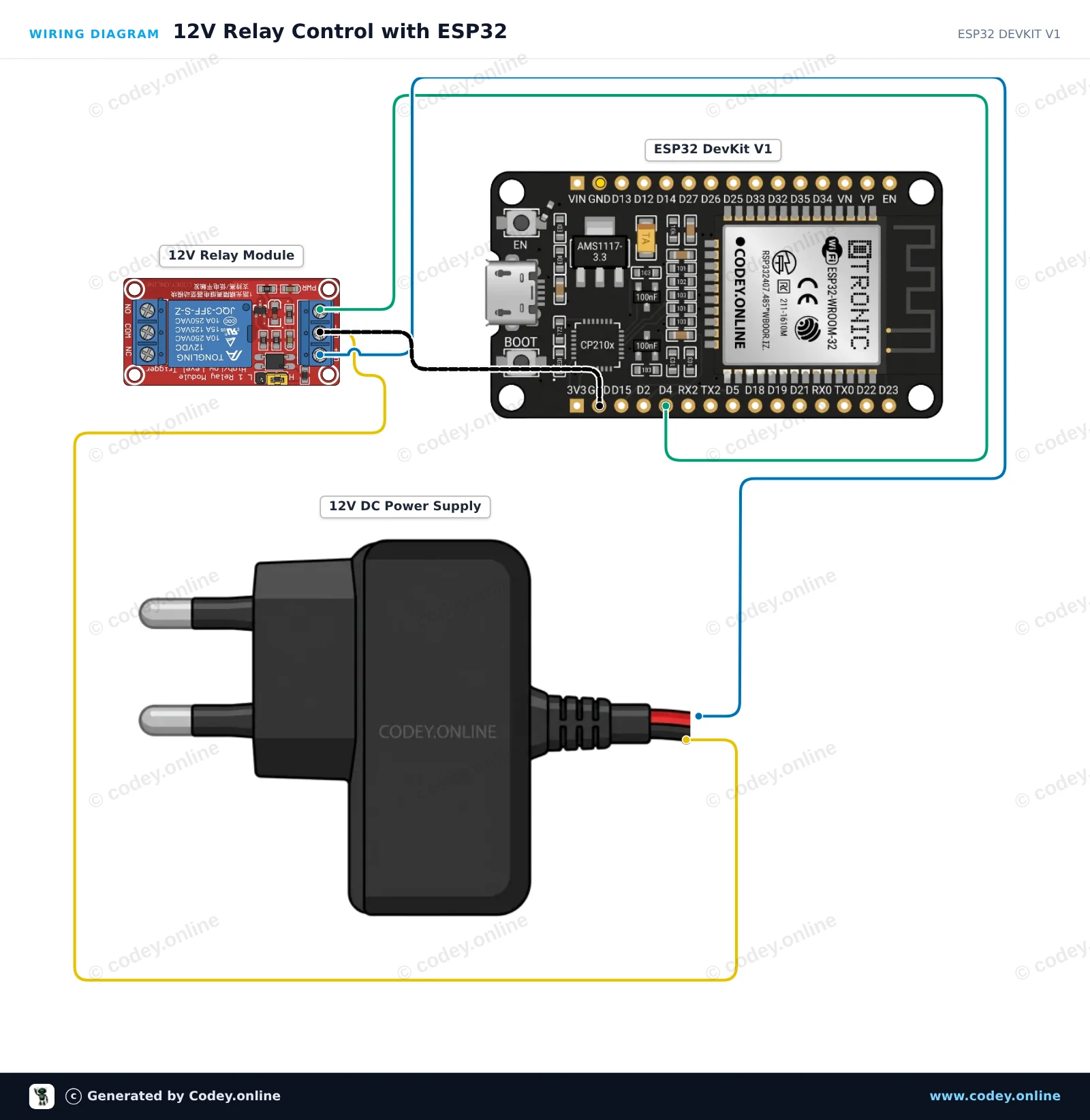
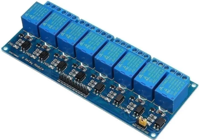
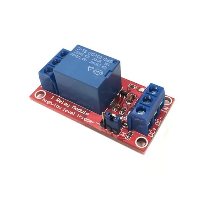
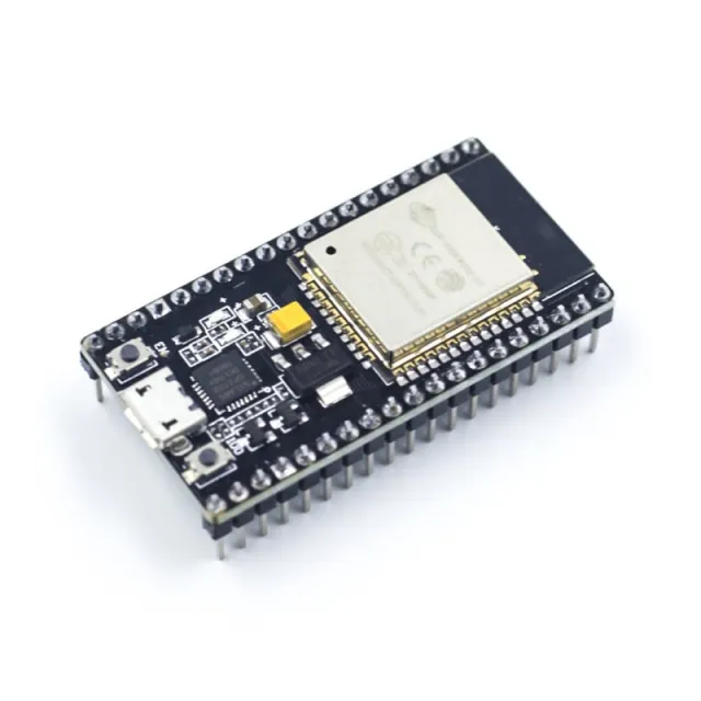
Voici comment connecter le Module relais 12 V à un Arduino UNO ou à un ESP32, avec un exemple de sketch que tu peux téléverser directement.
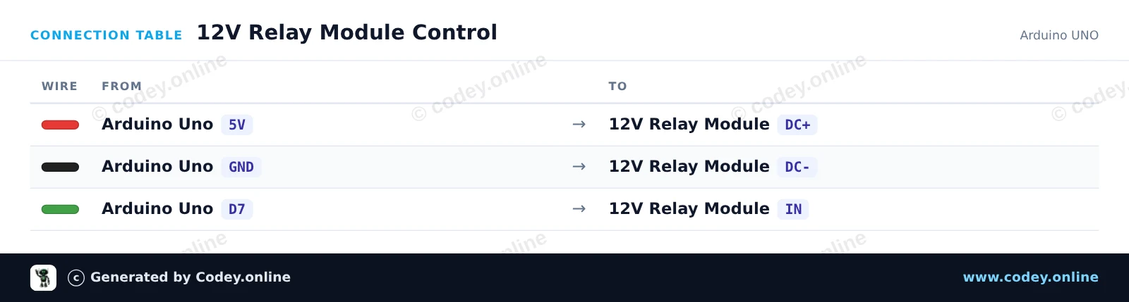
Ce projet montre comment contrôler un module relais 12V avec une Arduino Uno. Le sketch allume et éteint périodiquement le relais toutes les 2 secondes, en affichant l'état actuel dans le Serial Monitor. Un indicateur LED intégré sur le module s'allumera lorsque le relais est alimenté.
/*
 * ==================================================================
 *  Generated by Codey.online  —  https://www.codey.online
 * ==================================================================
 *  Project   : 12V Relay Module Control
 *  Board     : Arduino UNO (arduino:avr:uno)
 *  Parts     : Relais Module 12v AC250V 10A Relais 12v 1 relais LED indicator
 *  Libraries : none (built-in)
 *
 *  Codey Online is an AI-powered browser IDE for Arduino and ESP32.
 *  Describe your project and Codey writes the code, draws the wiring
 *  diagram and uploads it to your board, straight from the browser.
 *  This code is free to use, modify and share, without warranty.
 * ==================================================================
 */

// Pin configuration
const int RELAY_PIN = 7;

void setup() {
  // Initialize serial communication
  Serial.begin(115200);
  while (!Serial) {
    ; // Wait for serial port to connect
  }

  // Configure relay control pin
  pinMode(RELAY_PIN, OUTPUT);
  digitalWrite(RELAY_PIN, HIGH); // Default off (active-low module)

  Serial.println(F("12V Relay Module Demo Initialized"));
}

void loop() {
  // Activate relay (Low-level trigger)
  Serial.println(F("Relay: ON"));
  digitalWrite(RELAY_PIN, LOW);
  delay(2000);

  // Deactivate relay
  Serial.println(F("Relay: OFF"));
  digitalWrite(RELAY_PIN, HIGH);
  delay(2000);
}Wiring diagram and example code generated by Codey.online — https://www.codey.online
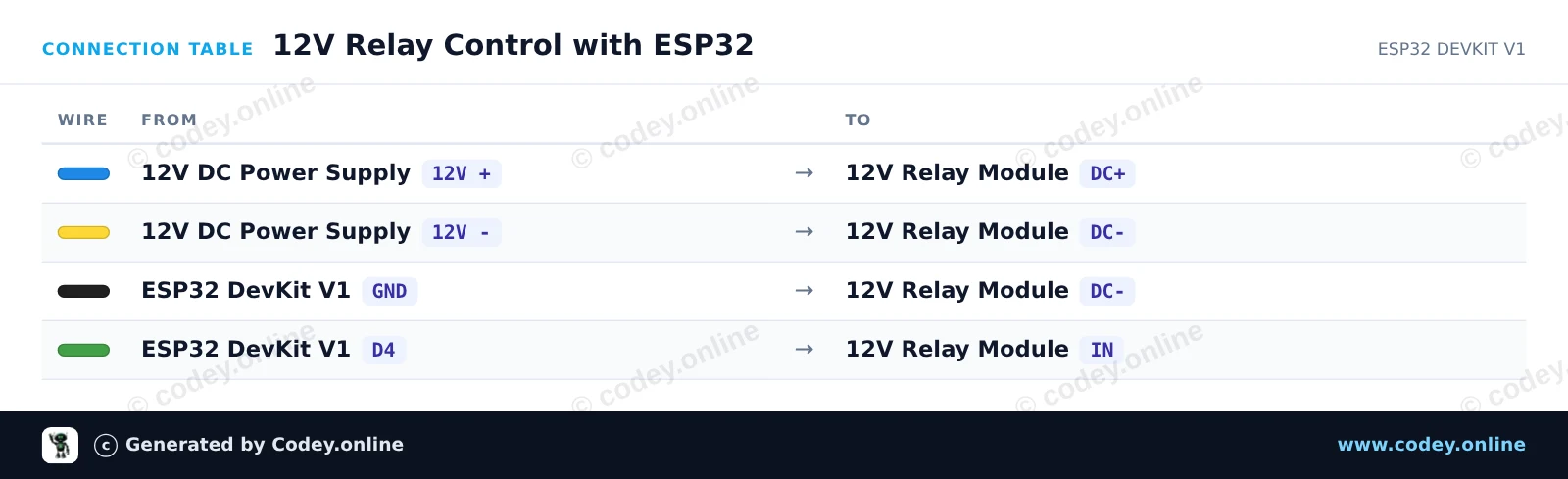
Ce projet montre comment commander un module relais 12V à un seul canal à l'aide d'un ESP32. La bobine du relais est alimentée par une alimentation externe 12V DC avec une masse commune à l'ESP32, et GPIO 4 active et désactive le relais toutes les deux secondes.
/*
 * ==================================================================
 *  Generated by Codey.online  —  https://www.codey.online
 * ==================================================================
 *  Project   : 12V Relay Control with ESP32
 *  Board     : ESP32 DEVKIT V1 (esp32:esp32:esp32doit-devkit-v1)
 *  Parts     : Relais Module 12v AC250V 10A Relais 12v 1 relais LED indicator
 *  Libraries : none (built-in)
 *
 *  Codey Online is an AI-powered browser IDE for Arduino and ESP32.
 *  Describe your project and Codey writes the code, draws the wiring
 *  diagram and uploads it to your board, straight from the browser.
 *  This code is free to use, modify and share, without warranty.
 * ==================================================================
 */

// Pin connected to relay control input
const int RELAY_PIN = 4;

void setup() {
  Serial.begin(115200);

  // Configure relay pin as output
  pinMode(RELAY_PIN, OUTPUT);
  digitalWrite(RELAY_PIN, LOW);

  Serial.println("ESP32 12V Relay Demo Started");
}

void loop() {
  // Turn relay ON
  Serial.println("Relay ON");
  digitalWrite(RELAY_PIN, HIGH);
  delay(2000);

  // Turn relay OFF
  Serial.println("Relay OFF");
  digitalWrite(RELAY_PIN, LOW);
  delay(2000);
}Wiring diagram and example code generated by Codey.online — https://www.codey.online






 English
  Nederlands
  Deutsch
  Italiano
  Español
  Suomi
Suomi  Polski
  Dansk
Dansk  Ελληνικά
  Български
  Čeština
  Hrvatski
  Aileen