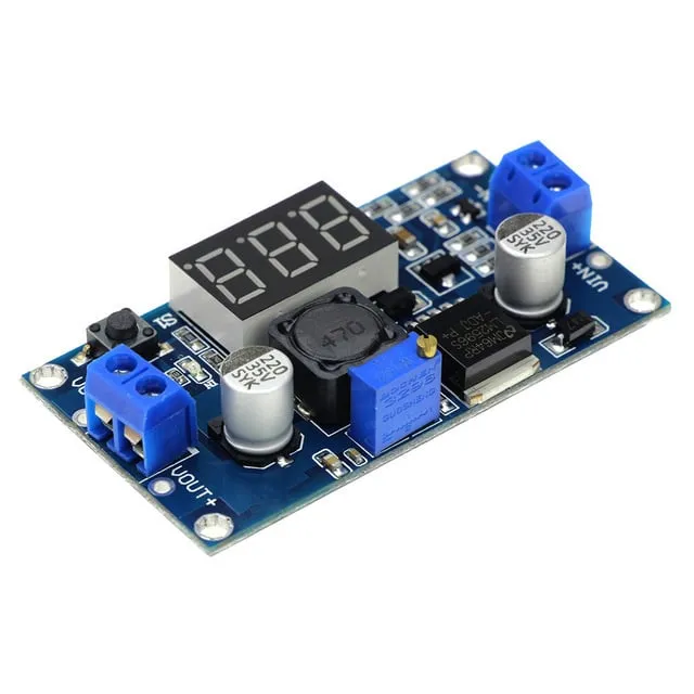
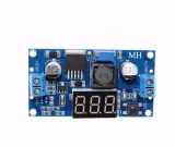
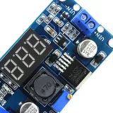
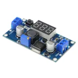
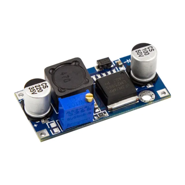
SKU: OT3593 Numéro d’article: NA068 EAN: 8720618489616

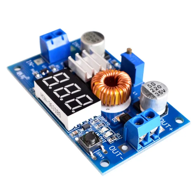
Tension d’entrée 4,0 ~ 40V. (La tension d’entrée doit être supérieure à la tension de sortie d’au moins 1,5 V)
Plage de tension de sortie réglable de 1,25V ~ 37V, réglage continu. (La tension d’entrée doit être supérieure à la tension de sortie de 1,5V)
Courant de sortie 3A, recommandation d’utilisation dans les 2,0A, un courant élevé est nécessaire pour améliorer la dissipation thermique.
Puissance de sortie 20W, 15W, améliorez la dissipation thermique.
Haut rendement de conversion, en moyenne 88% (le rendement est lié à la tension d’entrée et de sortie, au courant et à la pression)
Avec protection contre l’inversion de polarité
Taille 6.1 * 3.4 * 12 cm (L * l * H)
Dimensions
Longueur : 6,5cm
Largeur : 3,5cm
Hauteur : 1,2cm
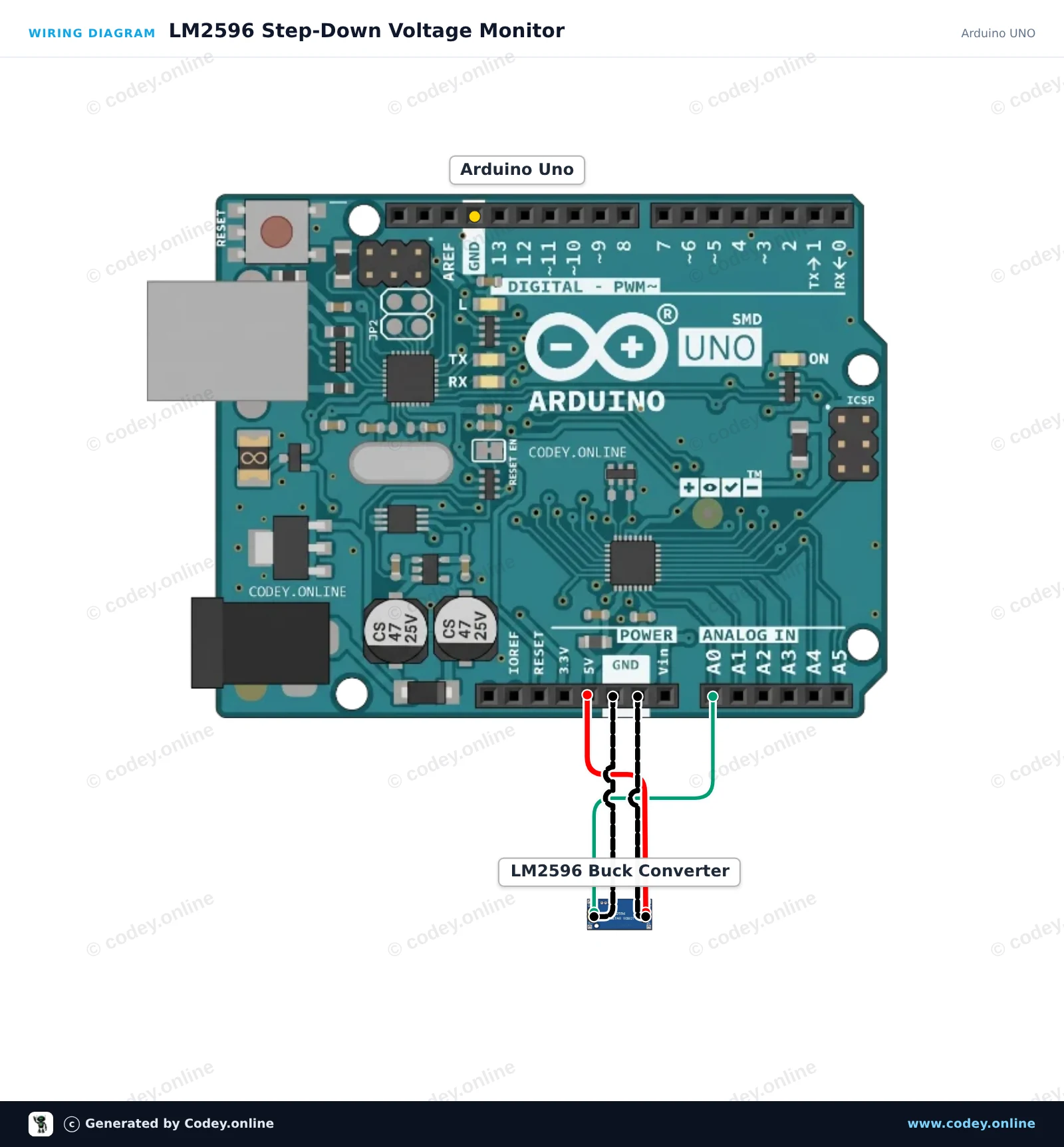
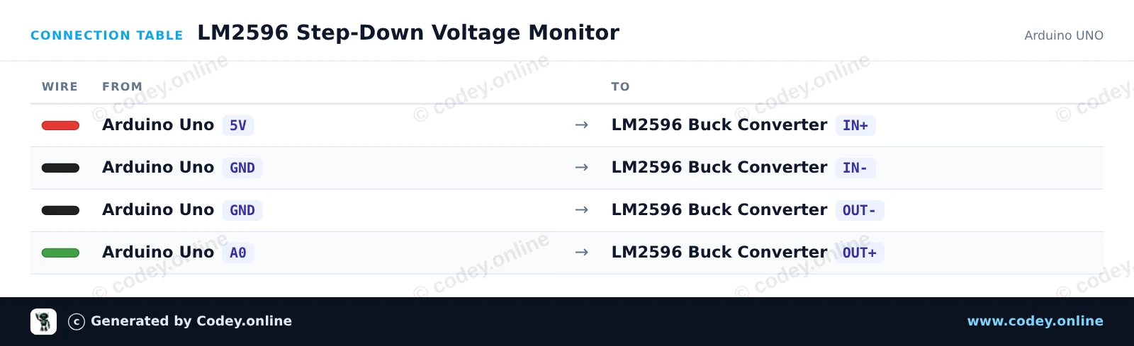
Voici comment connecter le LM2596S Convertisseur abaisseur réglable 4-40 V -> 1,25-37 V avec affichage voltmètre intégré à un Arduino UNO ou à un ESP32, avec un exemple de sketch que tu peux téléverser directement.
Ce projet mesure la tension de sortie d’un module convertisseur buck LM2596 à l’aide de l’entrée analogique A0 de l’Arduino. Alimentez l’entrée du module depuis le rail 5V de l’Arduino (ou avec une alimentation externe jusqu’à 40V) et tournez le potentiomètre intégré pour voir la tension de sortie mesurée changer dans le Serial Monitor.
/*
 * ==================================================================
 *  Generated by Codey.online  —  https://www.codey.online
 * ==================================================================
 *  Project   : LM2596 Step-Down Voltage Monitor
 *  Board     : Arduino UNO (arduino:avr:uno)
 *  Parts     : Adjustable Step-down Module 3-40VDC 1.5-35VDC LM2596
 *  Libraries : none (built-in)
 *
 *  Codey Online is an AI-powered browser IDE for Arduino and ESP32.
 *  Describe your project and Codey writes the code, draws the wiring
 *  diagram and uploads it to your board, straight from the browser.
 *  This code is free to use, modify and share, without warranty.
 * ==================================================================
 */

const int voltagePin = A0;

void setup() {
  Serial.begin(115200);
  while (!Serial) {
    ; // Wait for serial port to connect
  }
  Serial.println(F("LM2596 Step-Down Module Monitor"));
  Serial.println(F("Turn the onboard brass potentiometer to adjust output voltage."));
  Serial.println(F("-----------------------------------------------------------"));
}

void loop() {
  // Read the analog voltage (0 to 1023 corresponds to 0V to 5V)
  int rawValue = analogRead(voltagePin);
  float voltage = (rawValue * 5.0) / 1023.0;

  Serial.print(F("Raw ADC: "));
  Serial.print(rawValue);
  Serial.print(F(" | Output Voltage: "));
  Serial.print(voltage, 2);
  Serial.println(F(" V"));

  delay(500);
}Wiring diagram and example code generated by Codey.online — https://www.codey.online
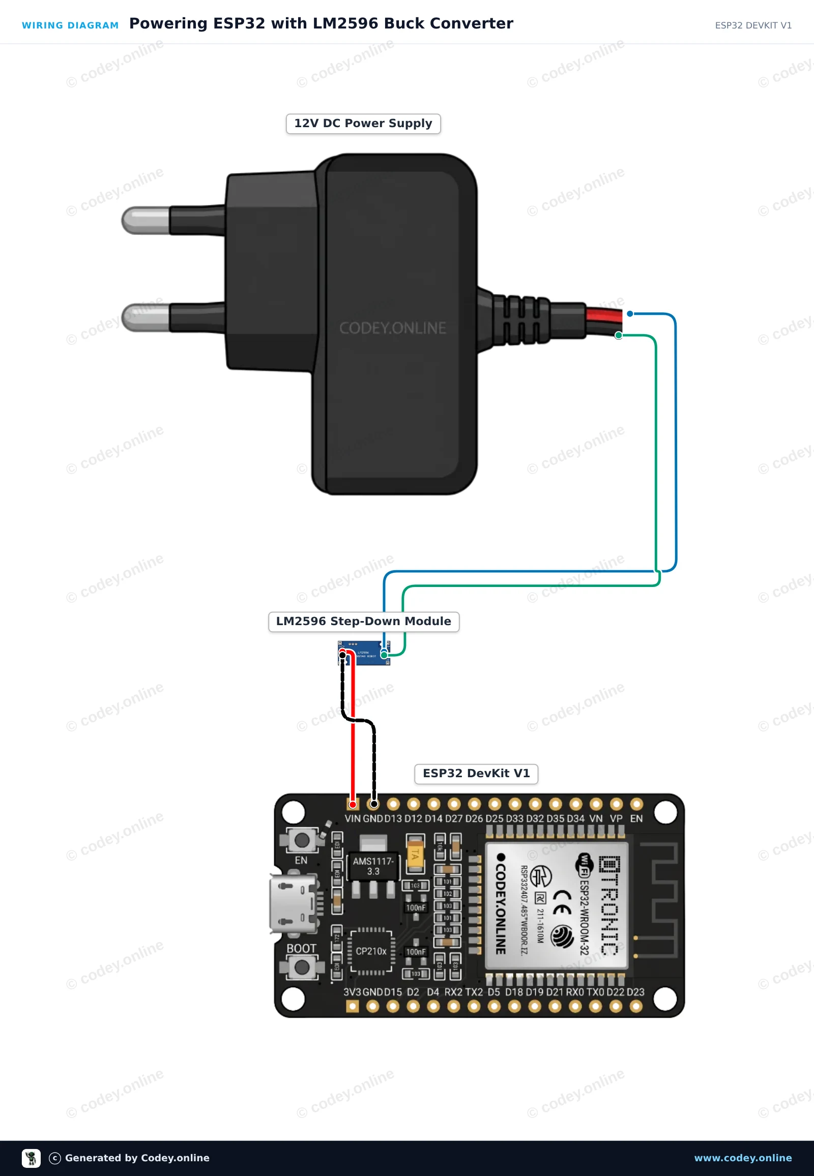
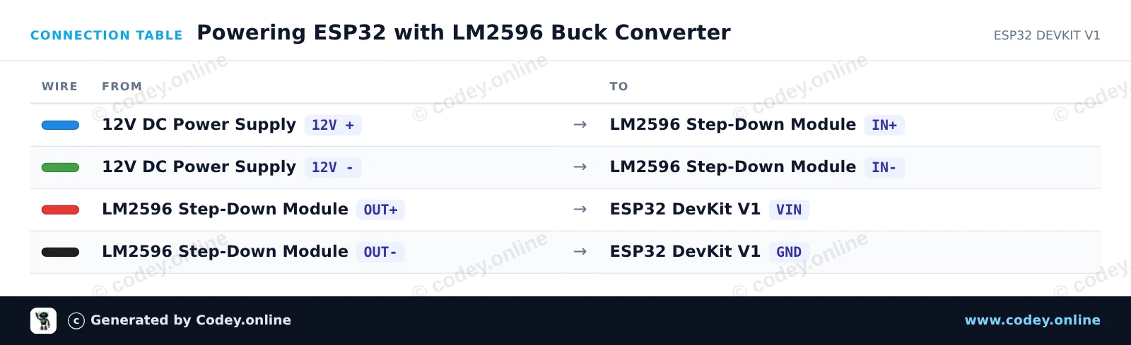
Ce circuit utilise un module abaisseur LM2596 pour réguler une entrée 12V DC vers un 5V stable pour la broche VIN de l'ESP32. Avant de connecter l'ESP32, réglez le trimmer intégré jusqu'à ce que la tension de sortie mesure exactement 5.0V avec un multimètre. Une fois connecté, l'ESP32 fait clignoter sa LED intégrée et affiche un message de heartbeat dans le Serial Monitor.
/*
 * ==================================================================
 *  Generated by Codey.online  —  https://www.codey.online
 * ==================================================================
 *  Project   : Powering ESP32 with LM2596 Buck Converter
 *  Board     : ESP32 DEVKIT V1 (esp32:esp32:esp32doit-devkit-v1)
 *  Parts     : Adjustable Step-down Module 3-40VDC 1.5-35VDC LM2596
 *  Libraries : none (built-in)
 *
 *  Codey Online is an AI-powered browser IDE for Arduino and ESP32.
 *  Describe your project and Codey writes the code, draws the wiring
 *  diagram and uploads it to your board, straight from the browser.
 *  This code is free to use, modify and share, without warranty.
 * ==================================================================
 */

const int LED_PIN = 2;
unsigned long counter = 0;

void setup() {
  Serial.begin(115200);
  pinMode(LED_PIN, OUTPUT);

  Serial.println("LM2596 Step-Down Powered ESP32 Started!");
  Serial.println("Ensure LM2596 output was calibrated to 5.0V before connecting to VIN.");
}

void loop() {
  digitalWrite(LED_PIN, HIGH);
  delay(500);
  digitalWrite(LED_PIN, LOW);
  delay(500);

  counter++;
  Serial.print("ESP32 running stably on buck regulator. Heartbeat count: ");
  Serial.println(counter);
}Wiring diagram and example code generated by Codey.online — https://www.codey.online






 English
  Nederlands
  Deutsch
  Italiano
  Español
  Suomi
Suomi  Polski
  Dansk
Dansk  Ελληνικά
  Български
  Čeština
  Hrvatski
  Aileen