SKU: OT6682 Numéro d’article: XR791 EAN: 8720828223468

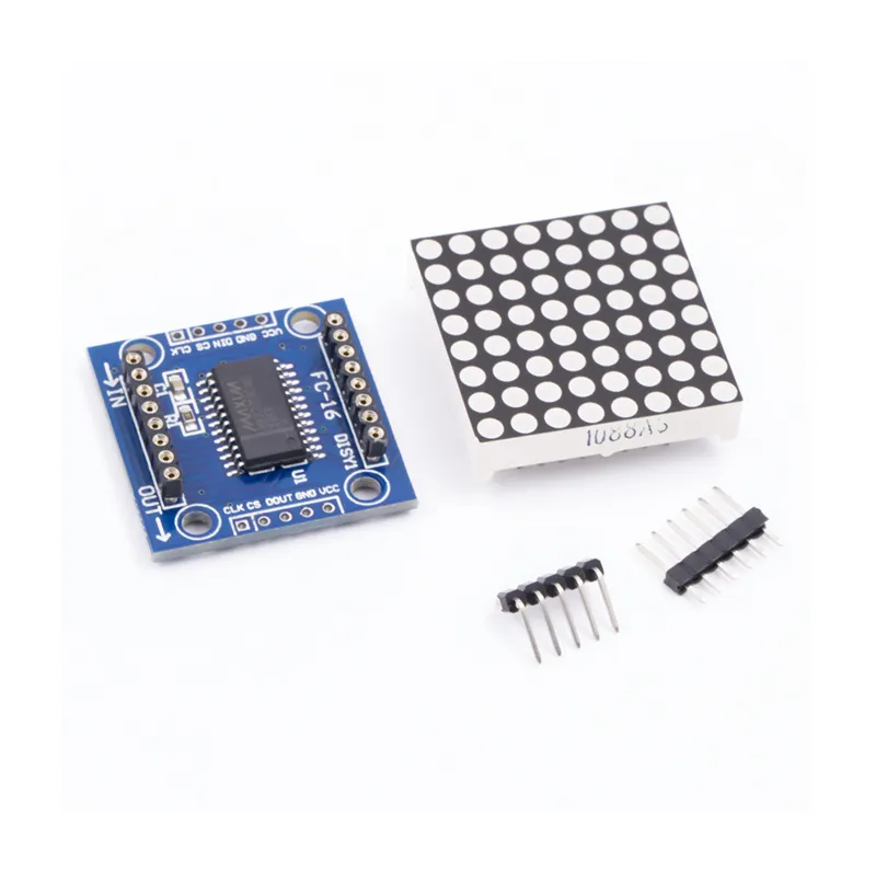
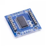
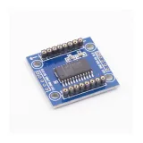
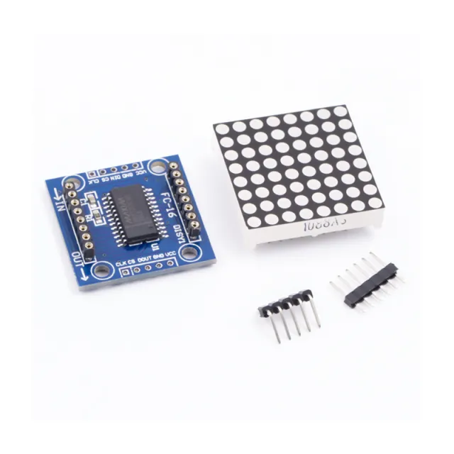
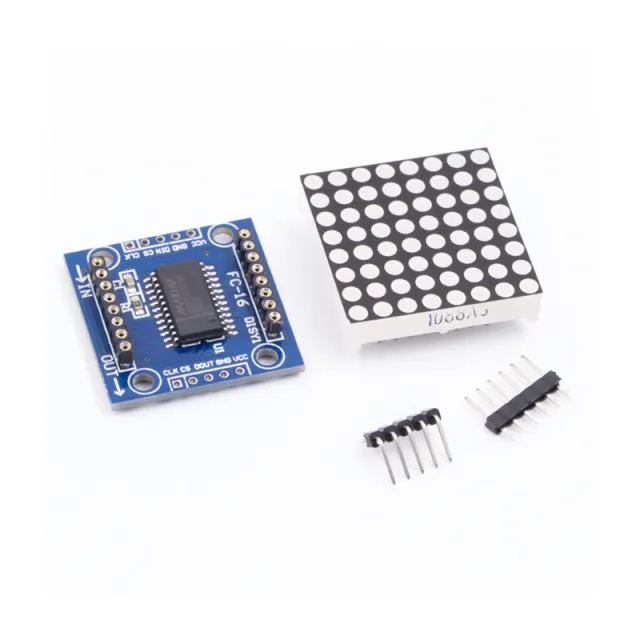
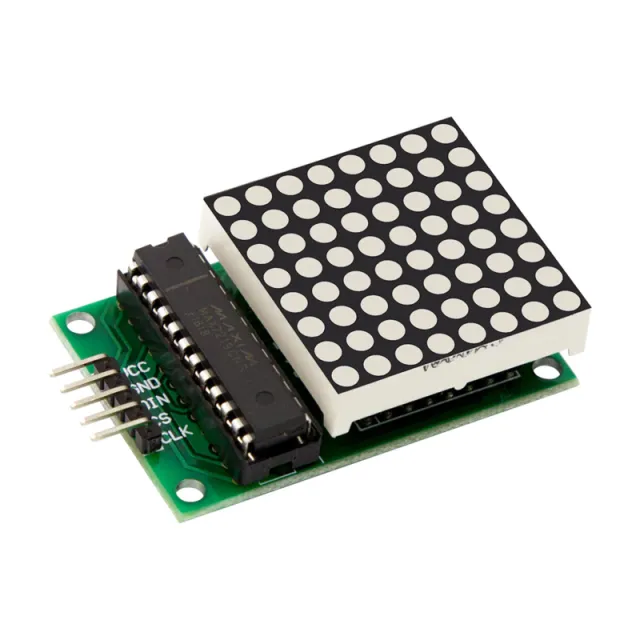
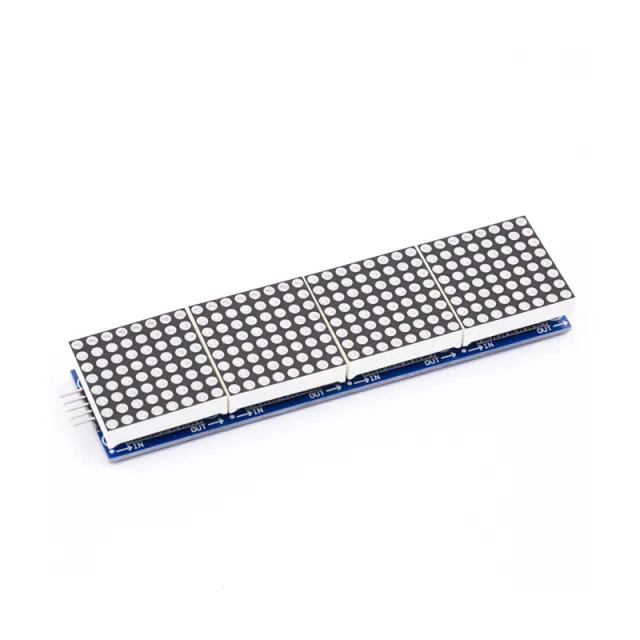
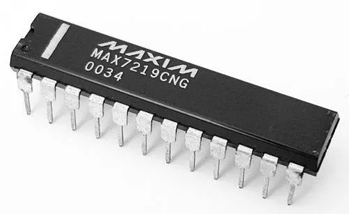
MAX7219 est un circuit intégré utilisé pour piloter des panneaux LED à cathode commune, des afficheurs à 7 segments et des indicateurs de niveau communiquant via l’interface SPI. Cette carte dispose d’un afficheur LED matriciel 8x8. Plusieurs modules peuvent être chaînés à l’aide de connexions par en-tête.
Spécifications :
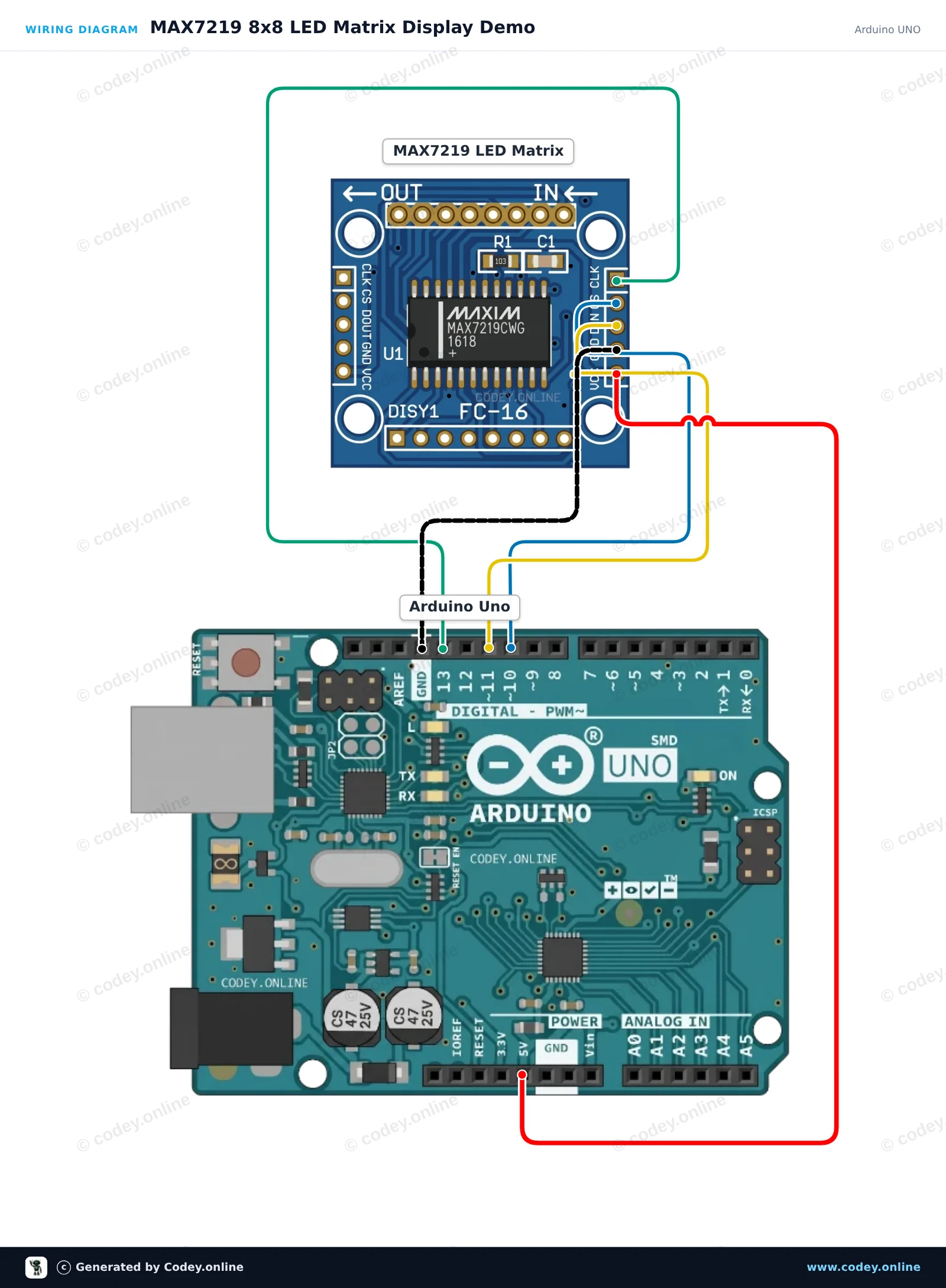
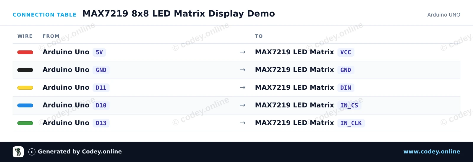
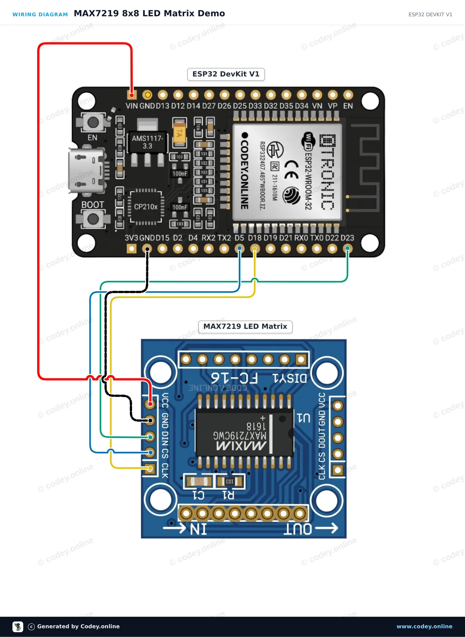
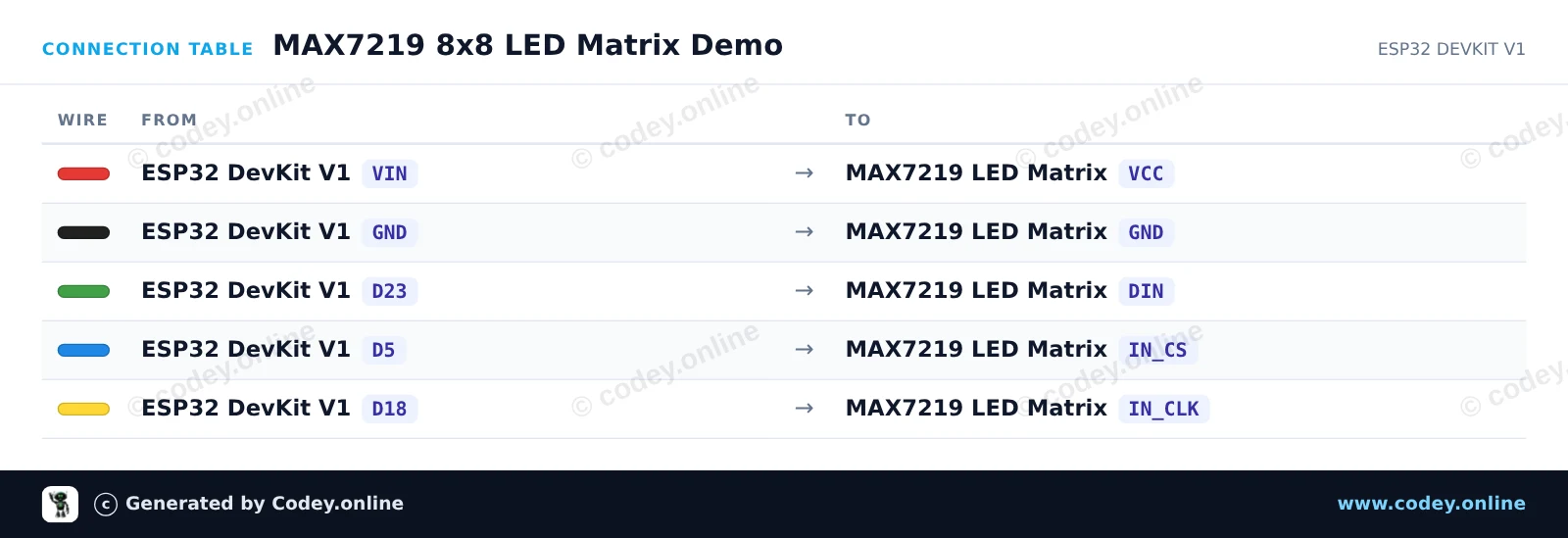
Voici comment connecter le Module matricielle LED MAX7219 verte à un Arduino UNO ou à un ESP32, avec un exemple de sketch que tu peux téléverser directement.
Ce projet montre comment contrôler une matrice LED 8x8 MAX7219 avec un Arduino Uno. Le sketch initialise l’afficheur et fait défiler l’affichage d’un cœur, d’un smiley et d’une animation de carré qui s’agrandit.
/*
 * ==================================================================
 *  Generated by Codey.online  —  https://www.codey.online
 * ==================================================================
 *  Project   : MAX7219 8x8 LED Matrix Display Demo
 *  Board     : Arduino UNO (arduino:avr:uno)
 *  Parts     : LED Matrix Module MAX7219
 *  Libraries : LedControl 1.0.6
 *
 *  Codey Online is an AI-powered browser IDE for Arduino and ESP32.
 *  Describe your project and Codey writes the code, draws the wiring
 *  diagram and uploads it to your board, straight from the browser.
 *  This code is free to use, modify and share, without warranty.
 * ==================================================================
 */

#include <LedControl.h>

const int DIN_PIN = 11;
const int CS_PIN  = 10;
const int CLK_PIN = 13;

LedControl lc = LedControl(DIN_PIN, CLK_PIN, CS_PIN, 1);

const byte HEART[8] = {
  B00000000,
  B01100110,
  B11111111,
  B11111111,
  B11111111,
  B01111110,
  B00111100,
  B00011000
};

const byte SMILE[8] = {
  B00111100,
  B01000010,
  B10100101,
  B10000001,
  B10100101,
  B10011001,
  B01000010,
  B00111100
};

void displayPattern(const byte pattern[8]) {
  for (int row = 0; row < 8; row++) {
    lc.setRow(0, row, pattern[row]);
  }
}

void setup() {
  Serial.begin(115200);
  Serial.println(F("MAX7219 LED Matrix Demo"));

  lc.shutdown(0, false);  // Wake up display
  lc.setIntensity(0, 8);   // Set brightness (0-15)
  lc.clearDisplay(0);
}

void loop() {
  // Show Heart
  displayPattern(HEART);
  delay(1500);

  // Show Smile
  displayPattern(SMILE);
  delay(1500);

  // Dot scan animation
  lc.clearDisplay(0);
  for (int row = 0; row < 8; row++) {
    for (int col = 0; col < 8; col++) {
      lc.setLed(0, row, col, true);
      delay(20);
    }
  }
  delay(500);
  lc.clearDisplay(0);
  delay(300);
}Bibliothèques nécessaires : LedControl 1.0.6
Wiring diagram and example code generated by Codey.online — https://www.codey.online
Ce projet utilise l'interface SPI matérielle de l'ESP32 pour piloter une matrice LED MAX7219 8x8 sans avoir besoin de bibliothèques externes. Le sketch initialise l'affichage et alterne entre un smiley, une icône de cœur et une animation de balayage des lignes.
/*
 * ==================================================================
 *  Generated by Codey.online  —  https://www.codey.online
 * ==================================================================
 *  Project   : MAX7219 8x8 LED Matrix Demo
 *  Board     : ESP32 DEVKIT V1 (esp32:esp32:esp32doit-devkit-v1)
 *  Parts     : LED Matrix Module MAX7219
 *  Libraries : none (built-in)
 *
 *  Codey Online is an AI-powered browser IDE for Arduino and ESP32.
 *  Describe your project and Codey writes the code, draws the wiring
 *  diagram and uploads it to your board, straight from the browser.
 *  This code is free to use, modify and share, without warranty.
 * ==================================================================
 */

#include <SPI.h>

const int CS_PIN = 5;

// MAX7219 register addresses
const byte REG_NOOP   = 0x00;
const byte REG_DIGIT0 = 0x01;
const byte REG_DECODE = 0x09;
const byte REG_INTEN  = 0x0A;
const byte REG_SCAN   = 0x0B;
const byte REG_SHUT   = 0x0C;
const byte REG_TEST   = 0x0F;

// 8x8 Bitmaps
const byte SMILE[8] = {
  0b00111100,
  0b01000010,
  0b10100101,
  0b10000001,
  0b10100101,
  0b10011001,
  0b01000010,
  0b00111100
};

const byte HEART[8] = {
  0b00000000,
  0b01100110,
  0b11111111,
  0b11111111,
  0b11111111,
  0b01111110,
  0b00111100,
  0b00011000
};

void max7219Send(byte reg, byte data) {
  digitalWrite(CS_PIN, LOW);
  SPI.transfer(reg);
  SPI.transfer(data);
  digitalWrite(CS_PIN, HIGH);
}

void clearDisplay() {
  for (byte i = 1; i <= 8; i++) {
    max7219Send(i, 0x00);
  }
}

void displayBitmap(const byte bitmap[8]) {
  for (byte i = 0; i < 8; i++) {
    max7219Send(i + 1, bitmap[i]);
  }
}

void setup() {
  Serial.begin(115200);
  pinMode(CS_PIN, OUTPUT);
  digitalWrite(CS_PIN, HIGH);

  // Initialize hardware SPI (SCK=18, MISO=19, MOSI=23, SS=5)
  SPI.begin(18, 19, 23, CS_PIN);

  // Configure MAX7219 registers
  max7219Send(REG_TEST, 0x00);   // Normal operation (display test off)
  max7219Send(REG_SCAN, 0x07);   // Scan all 8 digits/rows
  max7219Send(REG_DECODE, 0x00); // Raw matrix mode (no BCD decoding)
  max7219Send(REG_INTEN, 0x04);  // Medium brightness (0x00 to 0x0F)
  max7219Send(REG_SHUT, 0x01);   // Normal operation (wake up)
  clearDisplay();

  Serial.println("MAX7219 LED Matrix ready!");
}

void loop() {
  // Show Smiley Face
  displayBitmap(SMILE);
  delay(2000);

  // Show Heart Icon
  displayBitmap(HEART);
  delay(2000);

  // Row scan animation
  clearDisplay();
  for (byte r = 1; r <= 8; r++) {
    max7219Send(r, 0xFF);
    delay(100);
    max7219Send(r, 0x00);
  }
}Wiring diagram and example code generated by Codey.online — https://www.codey.online





 English
  Nederlands
  Deutsch
  Italiano
  Español
  Suomi
Suomi  Polski
  Dansk
Dansk  Ελληνικά
  Български
  Čeština
  Hrvatski
  Aileen