SKU: OT3260 Numéro d’article: NA445 EAN: 8720618231529

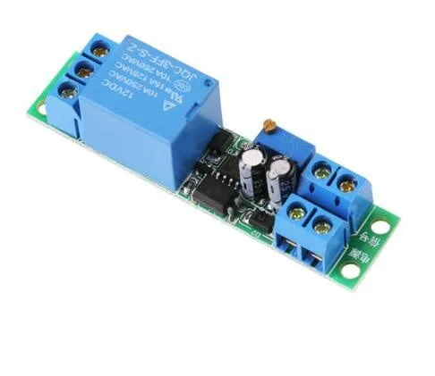
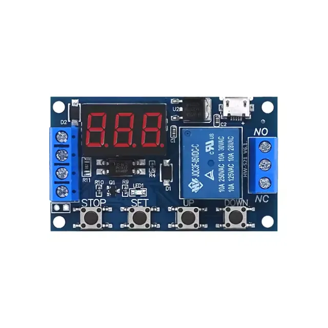
Ce module relais à temporisation fonctionne en 12V et peut être réglé à l’aide du potentiomètre à vis.
Tension de fonctionnement : DC 12V
Consommation de courant (lorsqu’il est activé) : ~46mA
Tension maximale via le relais : 30VDC ou 250VAC
Courant maximal via le relais : 10A
Temporisation réglable entre 0,1 et 25 secondes
Pour les instructions et un schéma de câblage, nous mettons à votre disposition le guide de démarrage rapide OTRONIC pour le module relais à temporisation réglable 12V.
Instructions :
Ce module relais à temporisation réglable OTRONIC® dispose d’une temporisation réglable à la coupure (retombée).
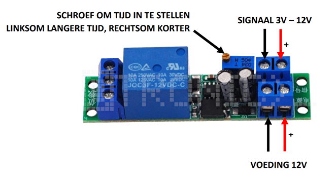
Tester le relais
Vous pouvez tester le temps réglé du relais sans commande externe.
Raccordez une alimentation 12V sur VCC et GND (alimentation). Sans signal, le relais effectuera une seule fois la
temporisation. Vous pouvez l’entendre au clic du relais.
Utilisez le potentiomètre à vis pour ajuster le temps. Tournez dans le sens antihoraire pour un temps plus long et dans le sens horaire
pour un temps plus court.
ATTENTION : plusieurs tours de vis sont nécessaires pour ajuster le temps.
Dimensions
Longueur : 6,68cm
Largeur : 1,6cm
Hauteur : 1,68cm
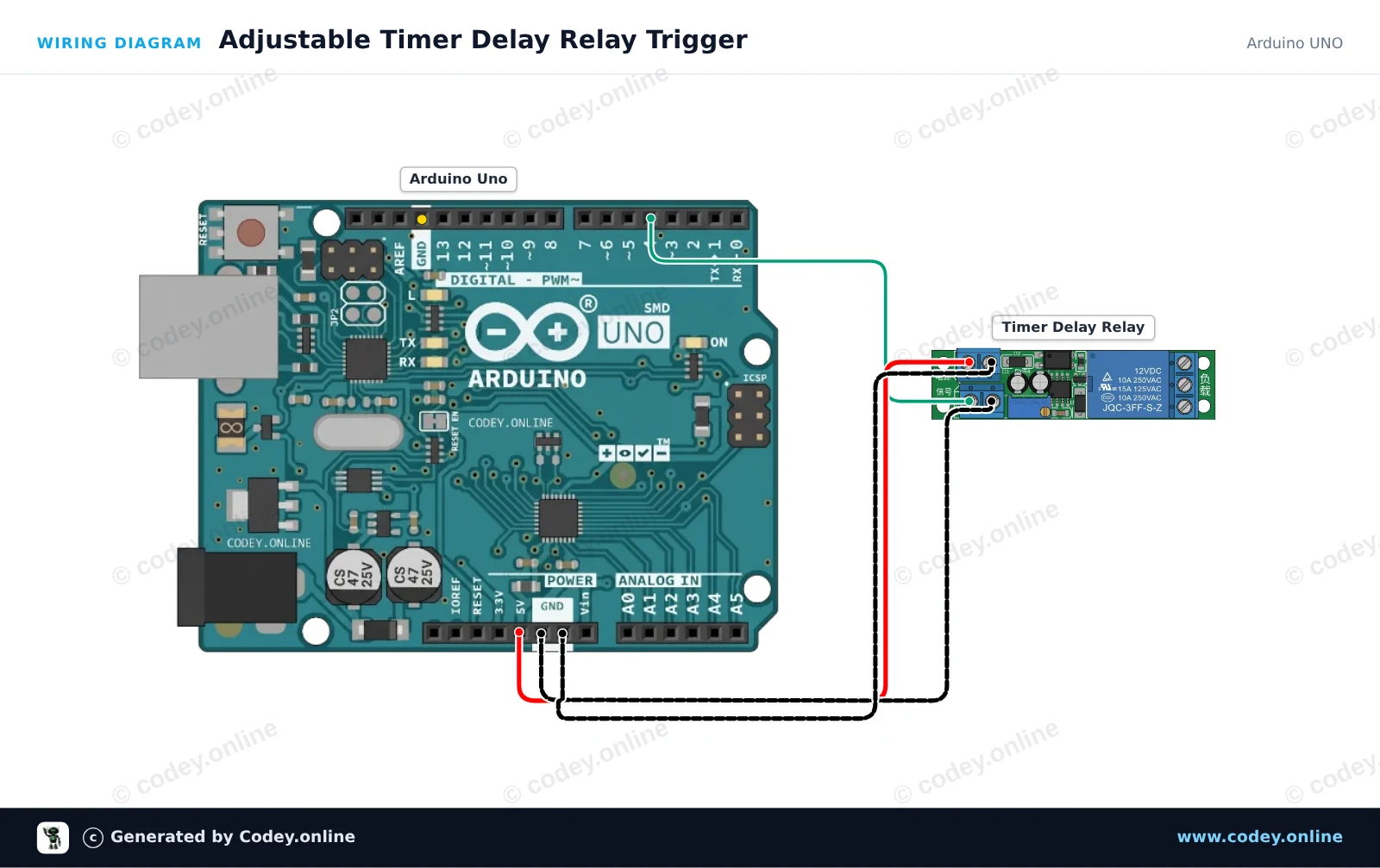
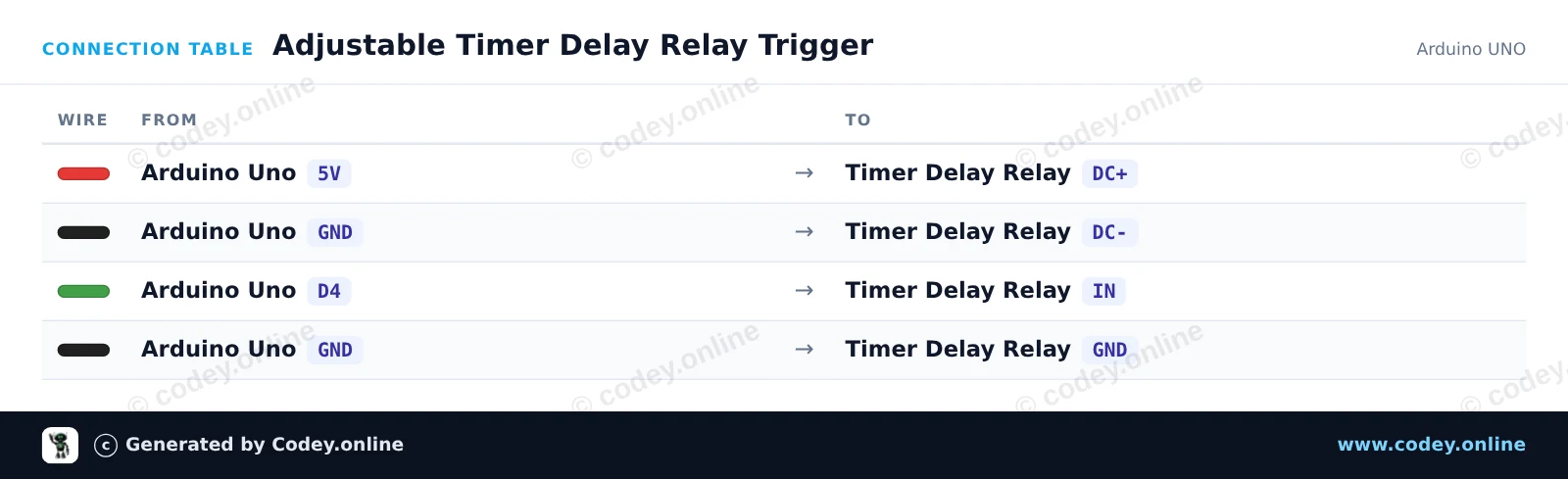
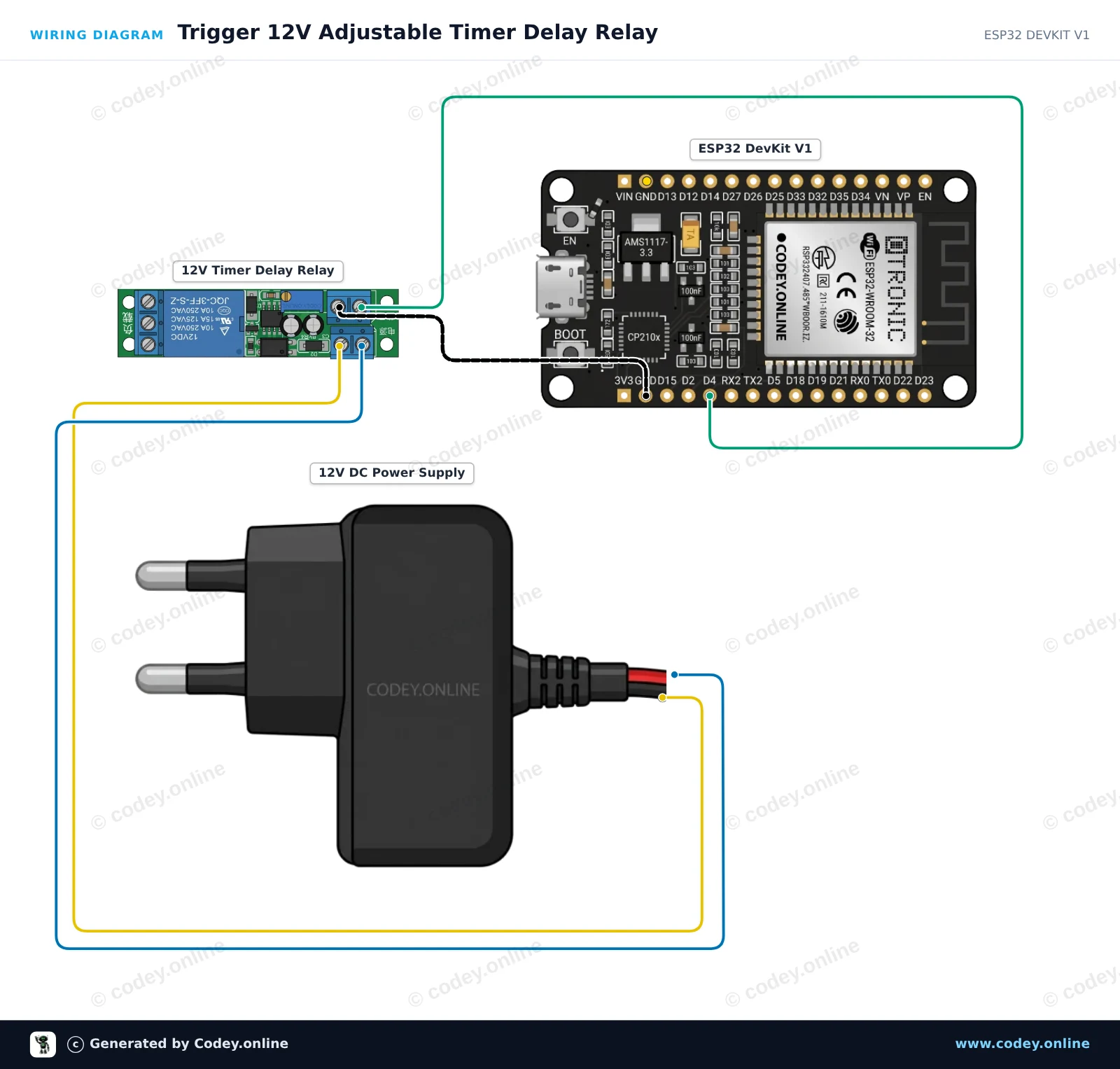
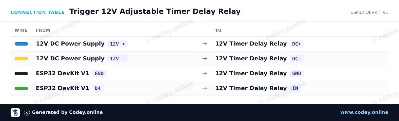
Voici comment connecter le Module relais à temporisation réglable 12 V à un Arduino UNO ou à un ESP32, avec un exemple de sketch que tu peux téléverser directement.
Ce projet montre comment déclencher un module relais à temporisation réglable à l’aide d’un Arduino Uno. L’Arduino envoie une courte impulsion depuis la broche numérique 4 vers la broche de déclenchement IN, activant le cycle de temporisation intégré du module. Réglez le potentiomètre sur le module relais pour modifier la durée d’activation du relais.
/*
 * ==================================================================
 *  Generated by Codey.online  —  https://www.codey.online
 * ==================================================================
 *  Project   : Adjustable Timer Delay Relay Trigger
 *  Board     : Arduino UNO (arduino:avr:uno)
 *  Parts     : DC 12V adjustable timer delay, time delay relay turn off switch module time relay time switch 0~25sec for smart home, automatic control
 *  Libraries : none (built-in)
 *
 *  Codey Online is an AI-powered browser IDE for Arduino and ESP32.
 *  Describe your project and Codey writes the code, draws the wiring
 *  diagram and uploads it to your board, straight from the browser.
 *  This code is free to use, modify and share, without warranty.
 * ==================================================================
 */

// Timer Delay Relay Module Demo
// Sends a trigger pulse to start the module's countdown delay.

const int triggerPin = 4;

void setup() {
  pinMode(triggerPin, OUTPUT);
  digitalWrite(triggerPin, LOW);

  Serial.begin(115200);
  Serial.println(F("Timer Delay Relay Demo Initialized."));
}

void loop() {
  Serial.println(F("Triggering relay delay cycle..."));

  // Send a 200 ms HIGH pulse to trigger the module
  digitalWrite(triggerPin, HIGH);
  delay(200);
  digitalWrite(triggerPin, LOW);

  Serial.println(F("Trigger sent. Waiting for delay cycle to complete..."));

  // Wait 10 seconds before triggering the next cycle
  delay(10000);
}Wiring diagram and example code generated by Codey.online — https://www.codey.online
Ce projet montre comment déclencher un module de relais temporisé 12V réglable à l’aide d’un ESP32. L’ESP32 envoie une brève impulsion de déclenchement pour lancer le compte à rebours, et le relais reste alimenté pendant la durée réglée par le potentiomètre intégré (0 à 25 seconds).
/*
 * ==================================================================
 *  Generated by Codey.online  —  https://www.codey.online
 * ==================================================================
 *  Project   : Trigger 12V Adjustable Timer Delay Relay
 *  Board     : ESP32 DEVKIT V1 (esp32:esp32:esp32doit-devkit-v1)
 *  Parts     : DC 12V adjustable timer delay, time delay relay turn off switch module time relay time switch 0~25sec for smart home, automatic control
 *  Libraries : none (built-in)
 *
 *  Codey Online is an AI-powered browser IDE for Arduino and ESP32.
 *  Describe your project and Codey writes the code, draws the wiring
 *  diagram and uploads it to your board, straight from the browser.
 *  This code is free to use, modify and share, without warranty.
 * ==================================================================
 */

// Pin connected to the IN trigger pin of the timer relay module
const int TRIGGER_PIN = 4;

void setup() {
  Serial.begin(115200);
  pinMode(TRIGGER_PIN, OUTPUT);
  digitalWrite(TRIGGER_PIN, LOW);

  Serial.println("ESP32 12V Timer Delay Relay Module Initialized");
  delay(1000);
}

void loop() {
  Serial.println("Sending trigger pulse...");

  // Send a 200 ms pulse to activate the timer
  digitalWrite(TRIGGER_PIN, HIGH);
  delay(200);
  digitalWrite(TRIGGER_PIN, LOW);

  Serial.println("Triggered! The relay will remain active for the duration set by the potentiometer.");

  // Wait 15 seconds before triggering the next cycle
  delay(15000);
}Wiring diagram and example code generated by Codey.online — https://www.codey.online







 English
  Nederlands
  Deutsch
  Italiano
  Español
  Suomi
Suomi  Polski
  Dansk
Dansk  Ελληνικά
  Български
  Čeština
  Hrvatski
  Aileen