SKU: OT5490 Numéro d’article: XW064 EAN: 8720828223642

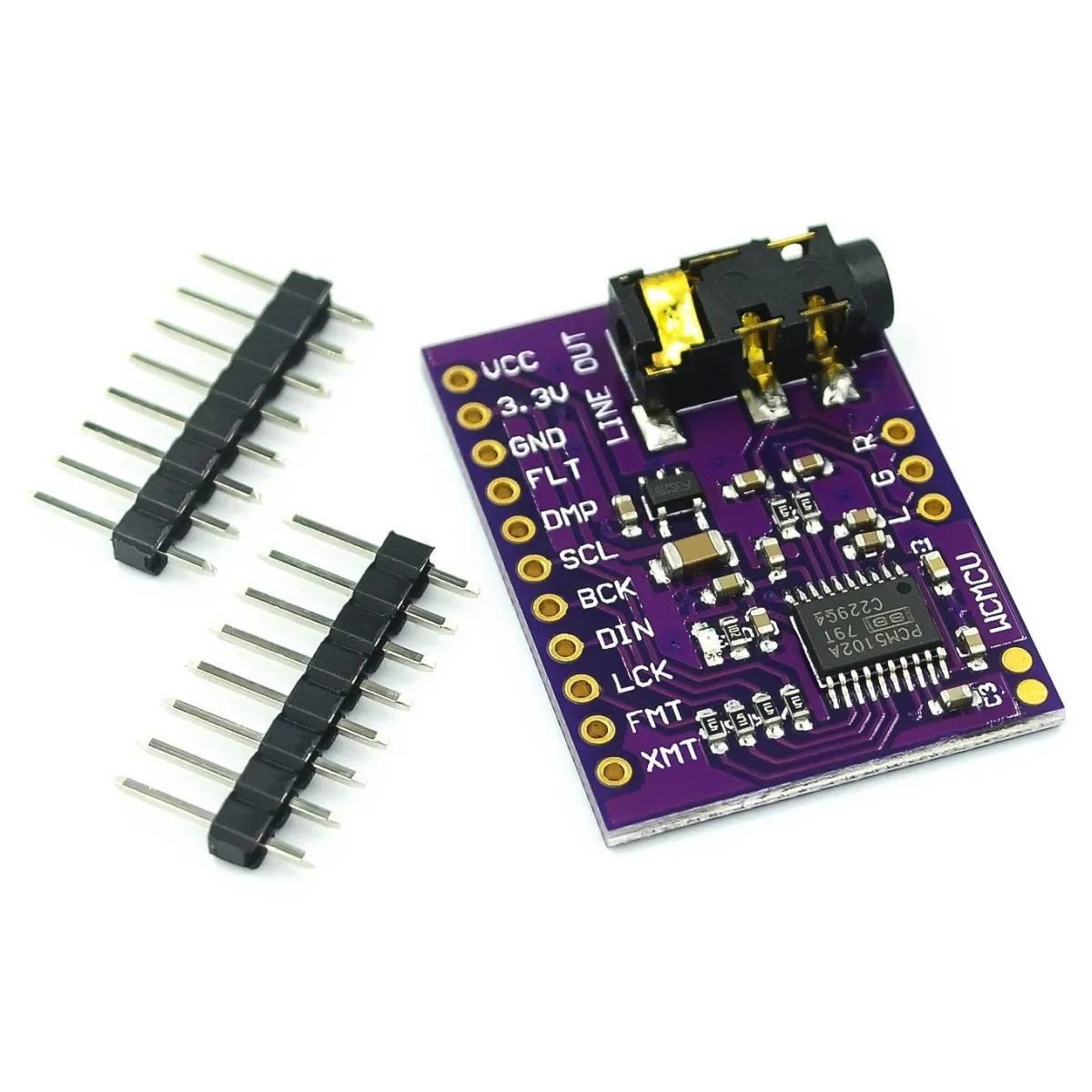
Ce PCM5102A est un module convertisseur numérique-analogique (DAC) principalement destiné à convertir des informations audio numériques en un signal audio analogique.
Spécifications techniques :
Résolution : Le PCM5102A prend en charge l’audio haute résolution avec des profondeurs de bits jusqu’à 32 bits et des fréquences d’échantillonnage jusqu’à 384 kHz.
Architecture Direct Path : L’une des caractéristiques uniques du PCM5102A est l’architecture "Direct Path", qui permet d’envoyer le signal directement vers la sortie sans avoir besoin d’un amplificateur opérationnel externe ni d’un condensateur de découplage DC.
Connectivité : Le PCM5102A utilise l’interface I2S, couramment employée dans les applications audio pour transmettre un signal audio numérique entre composants.
Tension d’alimentation : 3,3 V à 5 V.
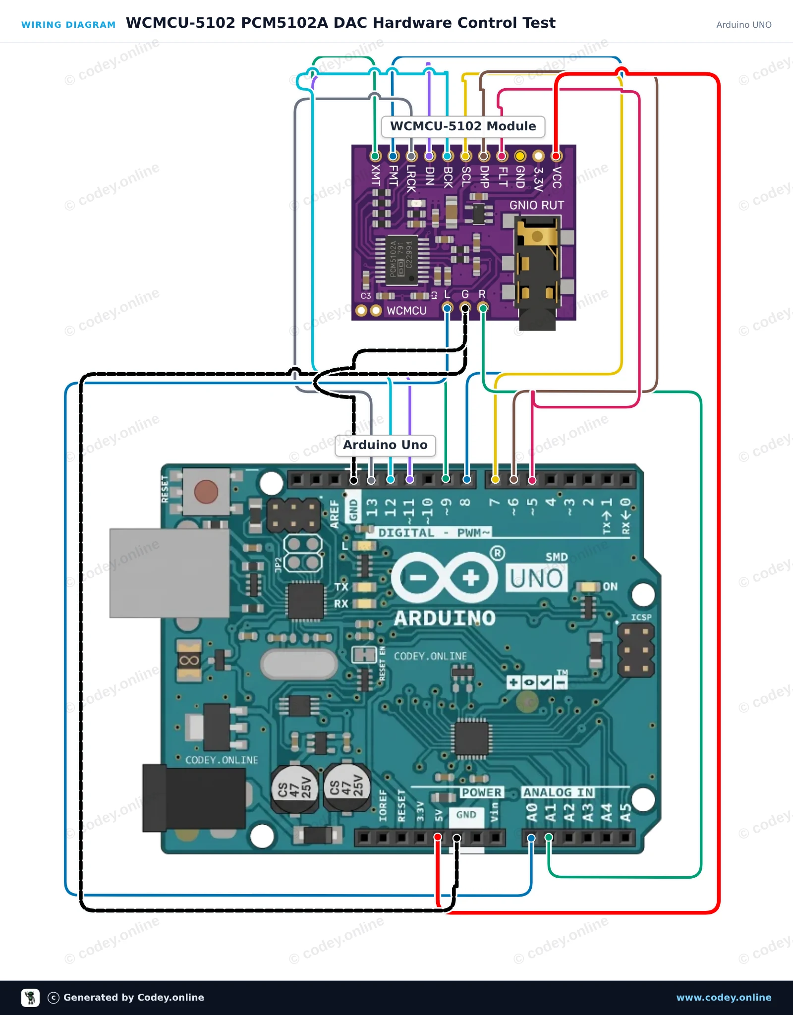
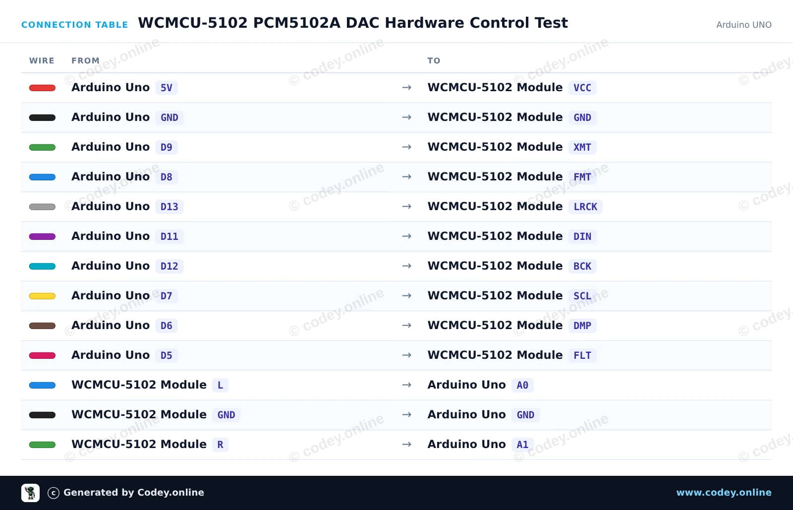
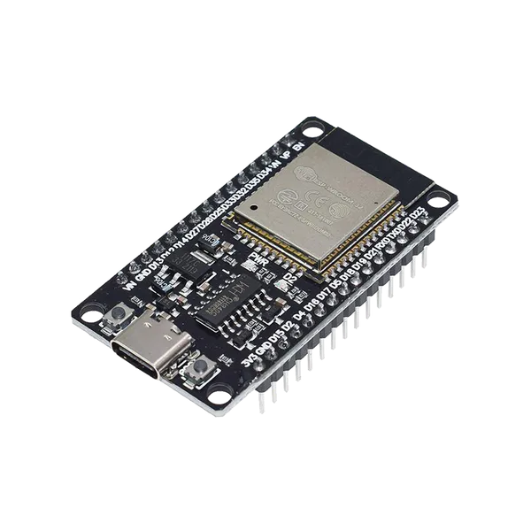
Voici comment connecter le Module stéréo DAC WCMCU-5102 convertisseur numérique vers analogique à un Arduino UNO ou à un ESP32, avec un exemple de sketch que tu peux téléverser directement.
Cet exemple montre comment alimenter et configurer le module DAC PCM5102A avec un Arduino Uno. Le sketch règle les broches de configuration matérielle (mute, format, system clock, de-emphasis et filter) et affiche l’état du module dans le Serial Monitor. Notez que la sortie audio analogique est de niveau ligne et doit être connectée à des headphones ou à un amplificateur, jamais directement à un speaker.
/*
 * ==================================================================
 *  Generated by Codey.online  —  https://www.codey.online
 * ==================================================================
 *  Project   : WCMCU-5102 PCM5102A DAC Hardware Control Test
 *  Board     : Arduino UNO (arduino:avr:uno)
 *  Parts     : WCMCU-5102 module
 *  Libraries : none (built-in)
 *
 *  Codey Online is an AI-powered browser IDE for Arduino and ESP32.
 *  Describe your project and Codey writes the code, draws the wiring
 *  diagram and uploads it to your board, straight from the browser.
 *  This code is free to use, modify and share, without warranty.
 * ==================================================================
 */

// WCMCU-5102 (PCM5102A) DAC Module Control Example
// Configures hardware control pins and toggles the unmute (XMT) signal.

const int PIN_XMT = 9;  // High = Unmute, Low = Soft mute
const int PIN_FMT = 8;  // Low = I2S format
const int PIN_SCL = 7;  // Low = Internal SCK generation
const int PIN_DMP = 6;  // Low = De-emphasis off
const int PIN_FLT = 5;  // Low = Normal latency filter

void setup() {
  Serial.begin(115200);
  while (!Serial);

  pinMode(PIN_XMT, OUTPUT);
  pinMode(PIN_FMT, OUTPUT);
  pinMode(PIN_SCL, OUTPUT);
  pinMode(PIN_DMP, OUTPUT);
  pinMode(PIN_FLT, OUTPUT);

  // Configure default PCM5102A operating modes
  digitalWrite(PIN_FMT, LOW);  // Set standard I2S format
  digitalWrite(PIN_SCL, LOW);  // Generate system clock internally
  digitalWrite(PIN_DMP, LOW);  // Disable de-emphasis filter
  digitalWrite(PIN_FLT, LOW);  // Normal latency filter
  digitalWrite(PIN_XMT, HIGH); // Unmute DAC output

  Serial.println(F("WCMCU-5102 DAC Initialized"));
  Serial.println(F("Configuration: I2S format, internal SCK, unmute active."));
  Serial.println(F("Note: Connect line outputs (L/R) to an amplifier or headphones."));
}

void loop() {
  // Periodic status display
  Serial.println(F("PCM5102A module active and unmuted."));
  delay(2000);
}Wiring diagram and example code generated by Codey.online — https://www.codey.online
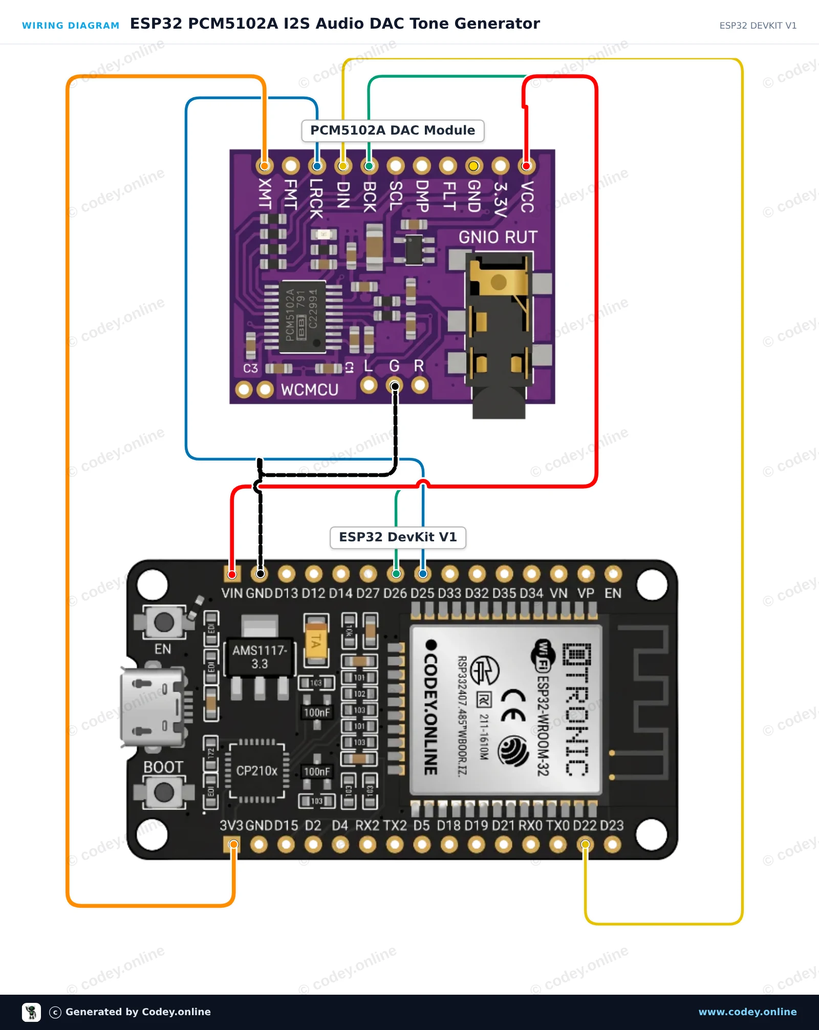
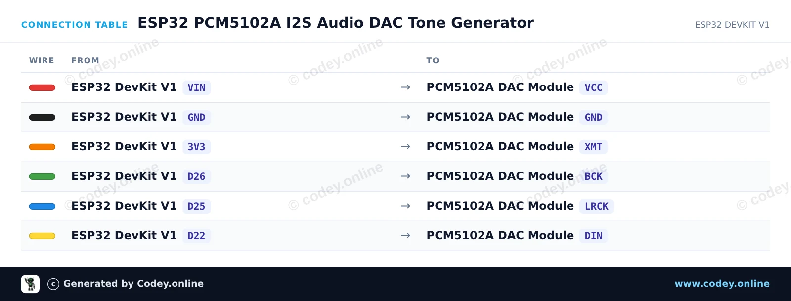
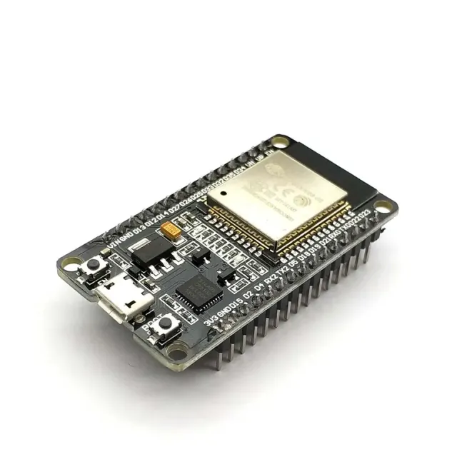
Ce projet connecte l'ESP32 à un DAC stéréo PCM5102A via l'interface audio numérique I2S pour générer un signal de test de 440 Hz d'une clarté cristalline. Branchez un casque standard 3.5mm ou un amplificateur niveau ligne sur la prise audio pour entendre la sortie stéréo. Le sketch synthétise une onde sinusoïdale propre en 16-bit à une fréquence d'échantillonnage de 44.1 kHz en utilisant le périphérique I2S matériel.
/*
 * ==================================================================
 *  Generated by Codey.online  —  https://www.codey.online
 * ==================================================================
 *  Project   : ESP32 PCM5102A I2S Audio DAC Tone Generator
 *  Board     : ESP32 DEVKIT V1 (esp32:esp32:esp32doit-devkit-v1)
 *  Parts     : WCMCU-5102 module
 *  Libraries : none (built-in)
 *
 *  Codey Online is an AI-powered browser IDE for Arduino and ESP32.
 *  Describe your project and Codey writes the code, draws the wiring
 *  diagram and uploads it to your board, straight from the browser.
 *  This code is free to use, modify and share, without warranty.
 * ==================================================================
 */

#include <Arduino.h>
#include "driver/i2s.h"
#include <math.h>

#define I2S_BCK_PIN   26
#define I2S_LRCK_PIN  25
#define I2S_DATA_PIN  22

const int SAMPLE_RATE = 44100;
const int TABLE_SIZE  = 128;
int16_t sineTable[TABLE_SIZE];

void setup() {
  Serial.begin(115200);
  Serial.println("ESP32 PCM5102A Audio Test");

  // Generate one period of a sine wave in a lookup table
  for (int i = 0; i < TABLE_SIZE; i++) {
    sineTable[i] = (int16_t)(sin(2.0 * PI * i / TABLE_SIZE) * 10000);
  }

  // Configure I2S peripheral
  i2s_config_t i2s_config = {
    .mode = (i2s_mode_t)(I2S_MODE_MASTER | I2S_MODE_TX),
    .sample_rate = SAMPLE_RATE,
    .bits_per_sample = I2S_BITS_PER_SAMPLE_16BIT,
    .channel_format = I2S_CHANNEL_FMT_RIGHT_LEFT,
    .communication_format = I2S_COMM_FORMAT_STAND_I2S,
    .intr_alloc_flags = ESP_INTR_FLAG_LEVEL1,
    .dma_buf_count = 8,
    .dma_buf_len = 64,
    .use_apll = false,
    .tx_desc_auto_clear = true
  };

  i2s_pin_config_t pin_config = {
    .bck_io_num = I2S_BCK_PIN,
    .ws_io_num = I2S_LRCK_PIN,
    .data_out_num = I2S_DATA_PIN,
    .data_in_num = I2S_PIN_NO_CHANGE
  };

  i2s_driver_install(I2S_NUM_0, &i2s_config, 0, NULL);
  i2s_set_pin(I2S_NUM_0, &pin_config);

  Serial.println("Playing continuous 440 Hz stereo tone...");
}

void loop() {
  size_t bytesWritten = 0;
  // Stream stereo samples (left and right channels)
  for (int i = 0; i < TABLE_SIZE; i++) {
    int16_t stereoSample[2] = { sineTable[i], sineTable[i] };
    i2s_write(I2S_NUM_0, stereoSample, sizeof(stereoSample), &bytesWritten, portMAX_DELAY);
  }
}Wiring diagram and example code generated by Codey.online — https://www.codey.online






 English
  Nederlands
  Deutsch
  Italiano
  Español
  Suomi
Suomi  Polski
  Dansk
Dansk  Ελληνικά
  Български
  Čeština
  Hrvatski
  Aileen