Commandé les jours ouvrables avant 14:00 = expédié le jour même. 30 jours pour changer d’avis 1 an de garantie

Schéma de câblage et exemple de code

Voici comment connecter le LCD TFT rond 1,28″ 240×240 (GC9A01, SPI) pour Arduino à un Arduino UNO ou à un ESP32, avec un exemple de sketch que tu peux téléverser directement.

Démo TFT LCD ronde GC9A01 de 1.28 pouce

Ce projet initialise et dessine des graphiques animés sur un écran TFT SPI rond de 1.28 pouce (contrôleur GC9A01). Il trace des anneaux concentriques colorés autour de l'écran circulaire et fait défiler en continu la couleur d'un cercle cible intérieur.

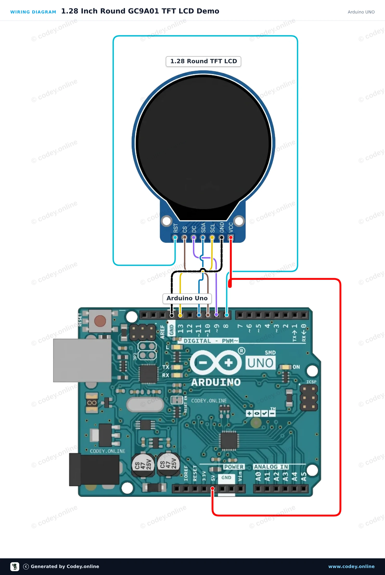
Schéma de câblage : LCD TFT rond 1,28″ 240×240 (GC9A01, SPI) pour Arduino sur un Arduino UNO
Schéma de câblage · Cliquez pour agrandir
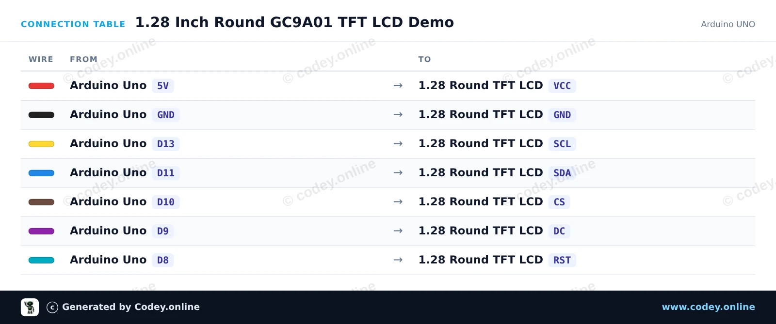
Tableau de câblage : LCD TFT rond 1,28″ 240×240 (GC9A01, SPI) pour Arduino sur un Arduino UNO
Tableau de câblage · Cliquez pour agrandir
1_28_Inch_Round_GC9A01_TFT_LCD_Demo.ino · compilé et testé
/*
 * ==================================================================
 *  Generated by Codey.online  —  https://www.codey.online
 * ==================================================================
 *  Project   : 1.28 Inch Round GC9A01 TFT LCD Demo
 *  Board     : Arduino UNO (arduino:avr:uno)
 *  Parts     : 1.28" Round TFT LCD 240x240 (GC9A01, SPI)
 *  Libraries : none (built-in)
 *
 *  Codey Online is an AI-powered browser IDE for Arduino and ESP32.
 *  Describe your project and Codey writes the code, draws the wiring
 *  diagram and uploads it to your board, straight from the browser.
 *  This code is free to use, modify and share, without warranty.
 * ==================================================================
 */

#include <SPI.h>

#define TFT_CS   10
#define TFT_DC    9
#define TFT_RST   8

#define COLOR_BLACK   0x0000
#define COLOR_BLUE    0x001F
#define COLOR_RED     0xF800
#define COLOR_GREEN   0x07E0
#define COLOR_CYAN    0x07FF
#define COLOR_MAGENTA 0xF81F
#define COLOR_YELLOW  0xFFE0
#define COLOR_WHITE   0xFFFF

const uint16_t palette[] = {COLOR_RED, COLOR_GREEN, COLOR_BLUE, COLOR_YELLOW, COLOR_CYAN, COLOR_MAGENTA};
int colorIndex = 0;

void writeCommand(uint8_t c) {
  digitalWrite(TFT_DC, LOW);
  digitalWrite(TFT_CS, LOW);
  SPI.transfer(c);
  digitalWrite(TFT_CS, HIGH);
}

void writeData(uint8_t d) {
  digitalWrite(TFT_DC, HIGH);
  digitalWrite(TFT_CS, LOW);
  SPI.transfer(d);
  digitalWrite(TFT_CS, HIGH);
}

void setWindow(uint16_t x0, uint16_t y0, uint16_t x1, uint16_t y1) {
  writeCommand(0x2A);
  writeData(x0 >> 8); writeData(x0 & 0xFF);
  writeData(x1 >> 8); writeData(x1 & 0xFF);
  writeCommand(0x2B);
  writeData(y0 >> 8); writeData(y0 & 0xFF);
  writeData(y1 >> 8); writeData(y1 & 0xFF);
  writeCommand(0x2C);
}

void fillScreen(uint16_t color) {
  setWindow(0, 0, 239, 239);
  digitalWrite(TFT_DC, HIGH);
  digitalWrite(TFT_CS, LOW);
  uint8_t hi = color >> 8;
  uint8_t lo = color & 0xFF;
  for (uint32_t i = 0; i < 240UL * 240UL; i++) {
    SPI.transfer(hi);
    SPI.transfer(lo);
  }
  digitalWrite(TFT_CS, HIGH);
}

void drawHLine(int16_t x, int16_t y, int16_t w, uint16_t color) {
  if (y < 0 || y >= 240 || x >= 240 || (x + w) <= 0) return;
  int16_t x1 = max(0, x);
  int16_t x2 = min(239, x + w - 1);
  int16_t len = x2 - x1 + 1;
  setWindow(x1, y, x2, y);
  digitalWrite(TFT_DC, HIGH);
  digitalWrite(TFT_CS, LOW);
  uint8_t hi = color >> 8;
  uint8_t lo = color & 0xFF;
  for (int16_t i = 0; i < len; i++) {
    SPI.transfer(hi);
    SPI.transfer(lo);
  }
  digitalWrite(TFT_CS, HIGH);
}

void fillCircle(int16_t x0, int16_t y0, int16_t r, uint16_t color) {
  for (int16_t dy = -r; dy <= r; dy++) {
    int16_t dx = sqrt((long)r * r - (long)dy * dy);
    drawHLine(x0 - dx, y0 + dy, dx * 2 + 1, color);
  }
}

void drawCircle(int16_t x0, int16_t y0, int16_t r, uint16_t color) {
  int16_t f = 1 - r, ddF_x = 1, ddF_y = -2 * r, x = 0, y = r;
  auto plot = [&](int16_t px, int16_t py) {
    if (px >= 0 && px < 240 && py >= 0 && py < 240) {
      setWindow(px, py, px, py);
      writeData(color >> 8);
      writeData(color & 0xFF);
    }
  };
  plot(x0, y0 + r); plot(x0, y0 - r); plot(x0 + r, y0); plot(x0 - r, y0);
  while (x < y) {
    if (f >= 0) { y--; ddF_y += 2; f += ddF_y; }
    x++; ddF_x += 2; f += ddF_x;
    plot(x0 + x, y0 + y); plot(x0 - x, y0 + y);
    plot(x0 + x, y0 - y); plot(x0 - x, y0 - y);
    plot(x0 + y, y0 + x); plot(x0 - y, y0 + x);
    plot(x0 + y, y0 - x); plot(x0 - y, y0 - x);
  }
}

void gc9a01Init() {
  pinMode(TFT_CS, OUTPUT);
  pinMode(TFT_DC, OUTPUT);
  pinMode(TFT_RST, OUTPUT);
  digitalWrite(TFT_CS, HIGH);

  digitalWrite(TFT_RST, HIGH);
  delay(10);
  digitalWrite(TFT_RST, LOW);
  delay(20);
  digitalWrite(TFT_RST, HIGH);
  delay(120);

  SPI.begin();
  SPI.beginTransaction(SPISettings(8000000, MSBFIRST, SPI_MODE0));

  writeCommand(0xEF);
  writeCommand(0xEB); writeData(0x14);
  writeCommand(0xFE);
  writeCommand(0xEF);
  writeCommand(0xEB); writeData(0x14);
  writeCommand(0x84); writeData(0x40);
  writeCommand(0x85); writeData(0xFF);
  writeCommand(0x86); writeData(0xFF);
  writeCommand(0x87); writeData(0xFF);
  writeCommand(0x88); writeData(0x0A);
  writeCommand(0x89); writeData(0x21);
  writeCommand(0x8A); writeData(0x00);
  writeCommand(0x8B); writeData(0x80);
  writeCommand(0x8C); writeData(0x01);
  writeCommand(0x8D); writeData(0x01);
  writeCommand(0x8E); writeData(0xFF);
  writeCommand(0x8F); writeData(0xFF);
  writeCommand(0xB6); writeData(0x00); writeData(0x00);
  writeCommand(0x3A); writeData(0x05);
  writeCommand(0x90); writeData(0x08); writeData(0x08); writeData(0x08); writeData(0x08);
  writeCommand(0xBD); writeData(0x06);
  writeCommand(0xBC); writeData(0x00);
  writeCommand(0xFF); writeData(0x60); writeData(0x01); writeData(0x04);
  writeCommand(0xC3); writeData(0x13);
  writeCommand(0xC4); writeData(0x13);
  writeCommand(0xC9); writeData(0x22);
  writeCommand(0xBE); writeData(0x11);
  writeCommand(0xE1); writeData(0x10); writeData(0x0E);
  writeCommand(0xDF); writeData(0x21); writeData(0x0C); writeData(0x02);
  writeCommand(0xF0); writeData(0x45); writeData(0x09); writeData(0x08); writeData(0x08); writeData(0x26); writeData(0x2A);
  writeCommand(0xF1); writeData(0x43); writeData(0x70); writeData(0x72); writeData(0x36); writeData(0x37); writeData(0x6F);
  writeCommand(0xF2); writeData(0x45); writeData(0x09); writeData(0x08); writeData(0x08); writeData(0x26); writeData(0x2A);
  writeCommand(0xF3); writeData(0x43); writeData(0x70); writeData(0x72); writeData(0x36); writeData(0x37); writeData(0x6F);
  writeCommand(0xED); writeData(0x1B); writeData(0x0B);
  writeCommand(0xAE); writeData(0x77);
  writeCommand(0xCD); writeData(0x63);
  writeCommand(0x70); writeData(0x07); writeData(0x07); writeData(0x04); writeData(0x0E); writeData(0x0F); writeData(0x09); writeData(0x07); writeData(0x08); writeData(0x03);
  writeCommand(0xE8); writeData(0x34);
  writeCommand(0x62); writeData(0x18); writeData(0x0D); writeData(0x71); writeData(0xED); writeData(0x70); writeData(0x70); writeData(0x18); writeData(0x0F); writeData(0x71); writeData(0xEF); writeData(0x70); writeData(0x70);
  writeCommand(0x63); writeData(0x18); writeData(0x11); writeData(0x71); writeData(0xF1); writeData(0x70); writeData(0x70); writeData(0x18); writeData(0x13); writeData(0x71); writeData(0xF3); writeData(0x70); writeData(0x70);
  writeCommand(0x64); writeData(0x28); writeData(0x29); writeData(0xF1); writeData(0x01); writeData(0xF1); writeData(0x00); writeData(0x07);
  writeCommand(0x66); writeData(0x3C); writeData(0x00); writeData(0xCD); writeData(0x67); writeData(0x45); writeData(0x45); writeData(0x10); writeData(0x00); writeData(0x00); writeData(0x00);
  writeCommand(0x67); writeData(0x00); writeData(0x3C); writeData(0x00); writeData(0x00); writeData(0x00); writeData(0x01); writeData(0x54); writeData(0x10); writeData(0x32); writeData(0x98);
  writeCommand(0x74); writeData(0x10); writeData(0x85); writeData(0x80); writeData(0x00); writeData(0x00); writeData(0x4E); writeData(0x00);
  writeCommand(0x98); writeData(0x3E); writeData(0x07);
  writeCommand(0x35);
  writeCommand(0x21);
  writeCommand(0x11);
  delay(120);
  writeCommand(0x29);
  delay(20);
}

void setup() {
  Serial.begin(115200);
  Serial.println(F("GC9A01 Round LCD Initializing..."));
  gc9a01Init();
  fillScreen(COLOR_BLACK);

  // Draw fixed outer rings
  drawCircle(120, 120, 118, COLOR_CYAN);
  drawCircle(120, 120, 116, COLOR_CYAN);
  drawCircle(120, 120, 100, COLOR_WHITE);
  drawCircle(120, 120, 80, COLOR_BLUE);
  drawCircle(120, 120, 60, COLOR_YELLOW);
  Serial.println(F("Display ready!"));
}

void loop() {
  // Pulse inner target circle with different colors
  fillCircle(120, 120, 40, palette[colorIndex]);
  Serial.print(F("Color index: "));
  Serial.println(colorIndex);

  colorIndex = (colorIndex + 1) % 6;
  delay(800);
}

Wiring diagram and example code generated by Codey.online — https://www.codey.online

Démo LCD TFT ronde GC9A01 1.28"

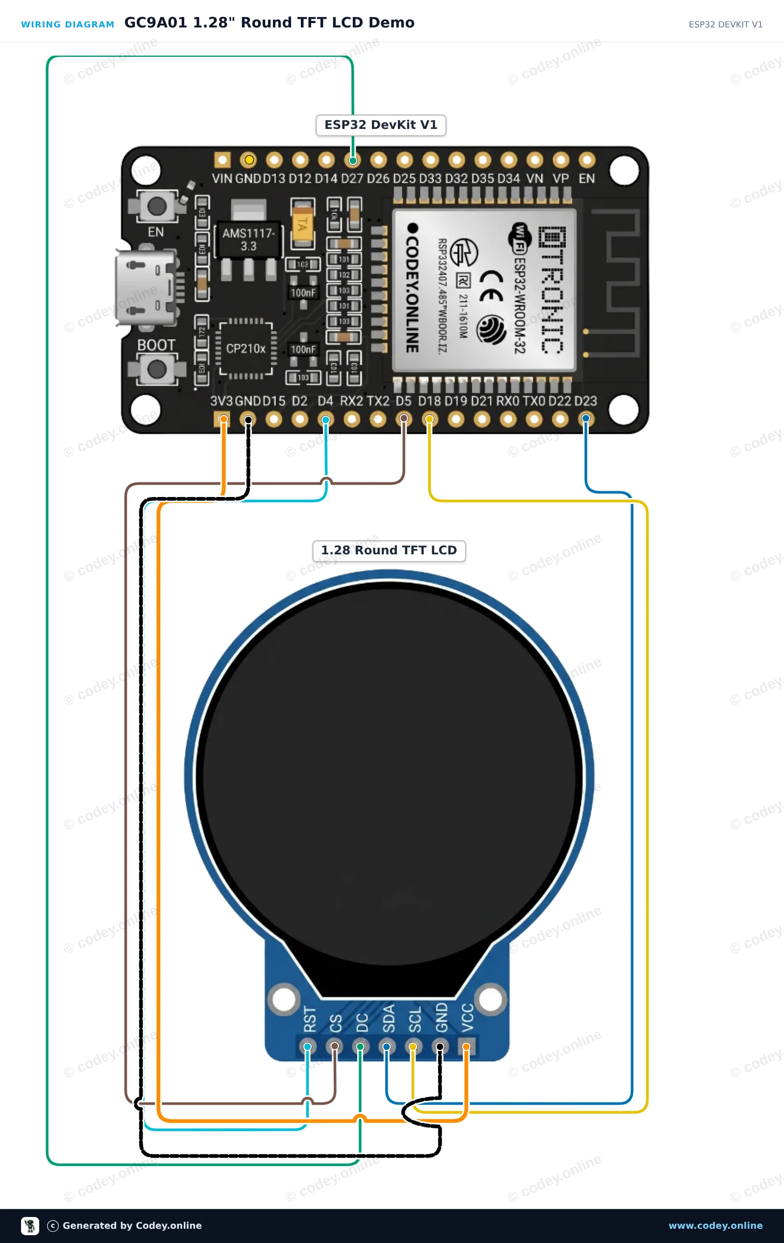
Ce projet connecte un écran LCD TFT rond GC9A01 de 1.28-inch à l'ESP32 via SPI. Le sketch initialise l'afficheur et dessine une disposition de jauge ronde personnalisée avec du texte et des indicateurs d'état mis à jour.

Schéma de câblage : LCD TFT rond 1,28″ 240×240 (GC9A01, SPI) pour Arduino sur un ESP32 DevKit V1
Schéma de câblage · Cliquez pour agrandir
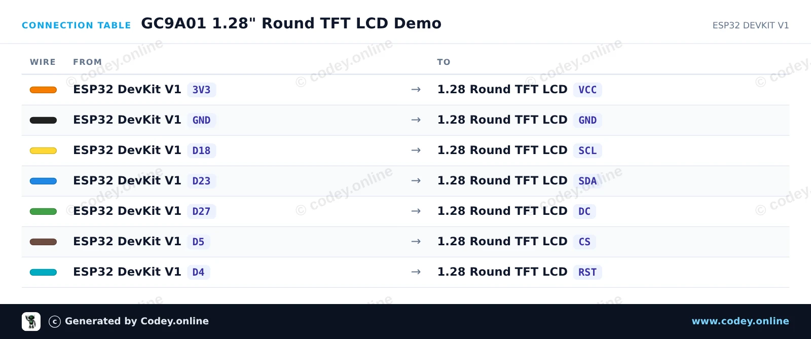
Tableau de câblage : LCD TFT rond 1,28″ 240×240 (GC9A01, SPI) pour Arduino sur un ESP32 DevKit V1
Tableau de câblage · Cliquez pour agrandir
GC9A01_1_28_Round_TFT_LCD_Demo.ino · compilé et testé
/*
 * ==================================================================
 *  Generated by Codey.online  —  https://www.codey.online
 * ==================================================================
 *  Project   : GC9A01 1.28" Round TFT LCD Demo
 *  Board     : ESP32 DEVKIT V1 (esp32:esp32:esp32doit-devkit-v1)
 *  Parts     : 1.28" Round TFT LCD 240x240 (GC9A01, SPI)
 *  Libraries : Adafruit GFX Library 1.12.6, Adafruit GC9A01A 1.1.1
 *
 *  Codey Online is an AI-powered browser IDE for Arduino and ESP32.
 *  Describe your project and Codey writes the code, draws the wiring
 *  diagram and uploads it to your board, straight from the browser.
 *  This code is free to use, modify and share, without warranty.
 * ==================================================================
 */

#include <SPI.h>
#include <Adafruit_GFX.h>
#include <Adafruit_GC9A01A.h>

#define TFT_CS   5
#define TFT_DC   27
#define TFT_RST  4

Adafruit_GC9A01A tft(TFT_CS, TFT_DC, TFT_RST);

void drawDial() {
  tft.fillScreen(GC9A01A_BLACK);
  
  // Draw outer colored rings
  tft.drawCircle(120, 120, 118, GC9A01A_CYAN);
  tft.drawCircle(120, 120, 115, GC9A01A_BLUE);
  tft.fillCircle(120, 120, 90, GC9A01A_NAVY);
  tft.fillCircle(120, 120, 80, GC9A01A_BLACK);

  // Centered labels
  tft.setTextColor(GC9A01A_WHITE);
  tft.setTextSize(2);
  tft.setCursor(65, 80);
  tft.println("GC9A01");

  tft.setTextSize(1);
  tft.setTextColor(GC9A01A_GREEN);
  tft.setCursor(75, 105);
  tft.println("ESP32 READY");
}

void setup() {
  Serial.begin(115200);
  Serial.println("Initializing GC9A01 Round Display...");

  tft.begin();
  tft.setRotation(0);
  drawDial();
  Serial.println("Display initialized!");
}

void loop() {
  static unsigned long lastUpdate = 0;
  static int counter = 0;

  if (millis() - lastUpdate >= 1000) {
    lastUpdate = millis();
    counter++;

    // Update counter display in the center
    tft.fillRect(60, 130, 120, 30, GC9A01A_BLACK);
    tft.setTextColor(GC9A01A_YELLOW);
    tft.setTextSize(3);
    tft.setCursor(95, 135);
    tft.printf("%02d", counter % 60);

    Serial.print("Counter: ");
    Serial.println(counter % 60);
  }
}

Bibliothèques nécessaires : Adafruit GFX Library 1.12.6, Adafruit GC9A01A 1.1.1

Wiring diagram and example code generated by Codey.online — https://www.codey.online

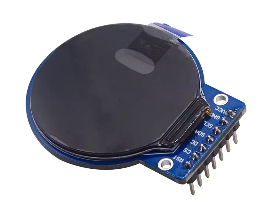
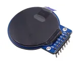
LCD TFT rond 1,28″ 240×240 (GC9A01, SPI) pour Arduino

Cet écran LCD TFT rond de 1,28 pouce est idéal pour les projets Arduino nécessitant un affichage clair et net. Avec une résolution de 240×240 pixels et un écran couleur IPS, il offre un affichage entièrement visible et éclatant sous tous les angles.

Caractéristiques principales

  • Taille de l'écran : rond 1,28 pouce
  • Résolution : 240×240 pixels
  • Type d'écran : écran couleur IPS pour de larges angles de vision
  • Puce pilote : GC9A01
  • Interface : 4-Pin SPI
  • Tension de fonctionnement : 2,8V à 3,3V
  • Pas des broches : 2,54 mm, 8 pins
  • Température de fonctionnement : -20℃ à 70℃
  • Humidité de fonctionnement : 5% à 95% RH

Spécifications techniques

  • Zone d'affichage : diamètre 32,4 mm
  • Dimensions du panneau : 35,6 × 38,1 × 1,5 mm
  • Dimensions du PCB : 44 × 36 × 5 mm
  • Angle entièrement visible pour une lisibilité optimale

Cet écran convient à diverses applications nécessitant un affichage couleur compact et de haute qualité. Grâce à l'interface SPI, il est facile à connecter à Arduino et à des microcontrôleurs similaires.

  • 1,28 pouce rond
  • 240×240 pixels
  • driver GC9A01
  • SPI 4 broches

Pourquoi choisir ce produit ?

  • Image nette – Écran couleur IPS avec affichage net.
  • Angles de vision larges – Entièrement visible sous tous les angles.
  • Facile à connecter – Convient à Arduino via SPI.
  • Écran compact – Pour les applications nécessitant un petit écran couleur.
Spécifications
Espacement des broches2,54 mm, 8 broches
Format d'écranRond de 1,28 pouce
Résolution240×240 pixels
Type d'écranÉcran couleur IPS pour de larges angles de vision
Puce piloteGC9A01
InterfaceSPI à 4 broches
Tension de fonctionnement2,8V à 3,3V
Température de fonctionnement-20℃ à 70℃
Humidité de fonctionnement5% à 95% RH
Zone d'affichage32,4 mm de diamètre
Dimensions du panneau35,6 × 38,1 × 1,5 mm
Dimensions du PCB44 × 36 × 5 mm

Avis

★★★★★ 5,0/5 1 avis
  • ★★★★★roan thieleAchat vérifié

    Très bel écran, difficile à coder correctement

Rédiger un avis
Votre note

Livraison & retours

Livraison

  • Colis avec suivi€ 6,353 jours ouvrés
  • Colis avec suivi€ 8,053 jours ouvrés
  • Colis avec suivi€ 9,153 jours ouvrés
  • Colis avec suivi€ 10,153 jours ouvrés
Tout sur la livraison

Retours

Pas satisfait ? Tu as 30 jours après réception pour renvoyer le produit.

Tout sur les retours

Récemment consultés