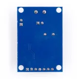
SKU: OT2083-D99 Numéro d’article: AA204 EAN: 4374044390615

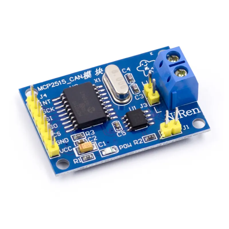
Le module CAN-bus MCP2515 convient aux projets Arduino et autres microcontrôleurs où vous souhaitez communiquer avec un système de bus CAN via le protocole SPI.
Prend en charge CAN V2.0B avec une vitesse de communication de 1 Mb/s.
Tension d'alimentation : 5V
Interface : contrôlable avec SPI
Dimensions : environ 2,8 x 4,8 cm
Dimensions
Longueur : 4cm
Largeur : 2,8cm
Hauteur : 1,2cm
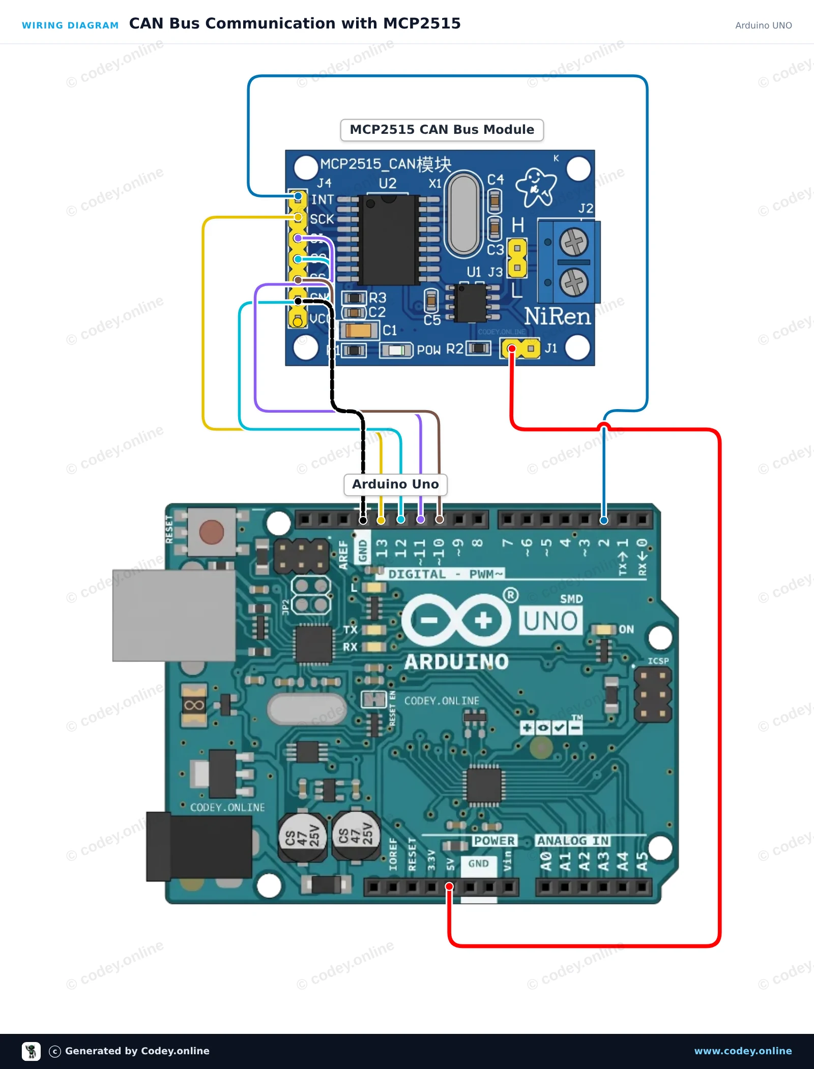
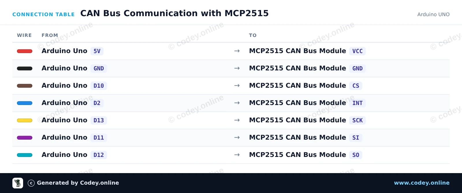
Voici comment connecter le Module CAN-bus MCP2515 SPI 5V à un Arduino UNO ou à un ESP32, avec un exemple de sketch que tu peux téléverser directement.
Connecte un module bus CAN MCP2515 à un Arduino Uno via hardware SPI. Le sketch initialise le contrôleur CAN à 500 kbps, envoie un message CAN de test toutes les 2 secondes et affiche toutes les trames reçues dans le Serial Monitor.
/*
 * ==================================================================
 *  Generated by Codey.online  —  https://www.codey.online
 * ==================================================================
 *  Project   : CAN Bus Communication with MCP2515
 *  Board     : Arduino UNO (arduino:avr:uno)
 *  Parts     : CAN-bus module MCP2515 SPI 5V
 *  Libraries : mcp_can 1.5.1
 *
 *  Codey Online is an AI-powered browser IDE for Arduino and ESP32.
 *  Describe your project and Codey writes the code, draws the wiring
 *  diagram and uploads it to your board, straight from the browser.
 *  This code is free to use, modify and share, without warranty.
 * ==================================================================
 */

#include <SPI.h>
#include <mcp_can.h>

const byte CAN_CS_PIN = 10;
const byte CAN_INT_PIN = 2;

MCP_CAN CAN(CAN_CS_PIN);

unsigned long lastSend = 0;

void setup() {
  Serial.begin(115200);
  pinMode(CAN_INT_PIN, INPUT);

  // Initialize MCP2515 with standard 8MHz crystal at 500 kbps
  if (CAN.begin(MCP_ANY, CAN_500KBPS, MCP_8MHZ) == CAN_OK) {
    Serial.println(F("MCP2515 initialized successfully!"));
  } else {
    Serial.println(F("MCP2515 initialization failed!"));
    while (1);
  }

  CAN.setMode(MCP_NORMAL);
  Serial.println(F("CAN controller ready in normal mode."));
}

void loop() {
  // Check for received CAN messages
  if (CAN.checkReceive() == CAN_MSGAVAIL) {
    unsigned long rxId;
    byte len = 0;
    byte rxBuf[8];

    CAN.readMsgBuf(&rxId, &len, rxBuf);

    Serial.print(F("RX -> ID: 0x"));
    Serial.print(rxId, HEX);
    Serial.print(F(" DLC: "));
    Serial.print(len);
    Serial.print(F(" Data: "));
    for (byte i = 0; i < len; i++) {
      if (rxBuf[i] < 0x10) Serial.print('0');
      Serial.print(rxBuf[i], HEX);
      Serial.print(' ');
    }
    Serial.println();
  }

  // Send a test packet every 2 seconds
  if (millis() - lastSend >= 2000) {
    lastSend = millis();
    byte txData[4] = {0xDE, 0xAD, 0xBE, 0xEF};
    byte sndStat = CAN.sendMsgBuf(0x100, 0, 4, txData);

    if (sndStat == CAN_OK) {
      Serial.println(F("TX -> Sent frame (ID: 0x100, Data: DE AD BE EF)"));
    } else {
      Serial.println(F("TX -> Error sending message"));
    }
  }
}Bibliothèques nécessaires : mcp_can 1.5.1
Wiring diagram and example code generated by Codey.online — https://www.codey.online
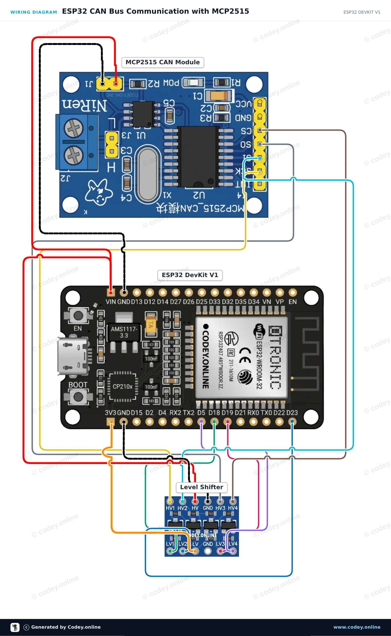
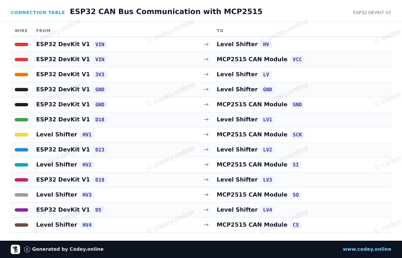
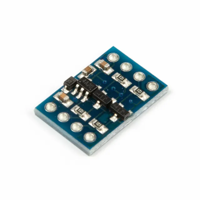
Ce circuit relie un ESP32 à un module CAN-bus MCP2515 via SPI, à l’aide d’un convertisseur de niveau bidirectionnel à 4 canaux pour protéger la logique 3.3V de l’ESP32 contre le module 5V. Le sketch initialise le contrôleur CAN à 500 kbps, envoie une trame de données CAN de test toutes les deux secondes et affiche tous les messages CAN bus reçus dans le Serial Monitor.
/*
 * ==================================================================
 *  Generated by Codey.online  —  https://www.codey.online
 * ==================================================================
 *  Project   : ESP32 CAN Bus Communication with MCP2515
 *  Board     : ESP32 DEVKIT V1 (esp32:esp32:esp32doit-devkit-v1)
 *  Parts     : CAN-bus module MCP2515 SPI 5V
 *  Libraries : mcp_can 1.5.1
 *
 *  Codey Online is an AI-powered browser IDE for Arduino and ESP32.
 *  Describe your project and Codey writes the code, draws the wiring
 *  diagram and uploads it to your board, straight from the browser.
 *  This code is free to use, modify and share, without warranty.
 * ==================================================================
 */

#include <SPI.h>
#include <mcp_can.h>

const int CAN_CS_PIN = 5;
MCP_CAN CAN0(CAN_CS_PIN);

void setup() {
  Serial.begin(115200);
  while (!Serial);

  // Initialize MCP2515 running at 8MHz clock and 500kbps CAN baud rate
  if (CAN0.begin(MCP_ANY, CAN_500KBPS, MCP_8MHZ) == CAN_OK) {
    Serial.println("MCP2515 Initialized Successfully!");
  } else {
    Serial.println("Error Initializing MCP2515...");
  }

  CAN0.setMode(MCP_NORMAL);
}

void loop() {
  // Prepare sample data payload (8 bytes)
  byte data[8] = {0x11, 0x22, 0x33, 0x44, 0x55, 0x66, 0x77, 0x88};

  // Send CAN message with standard ID 0x100
  byte sndStat = CAN0.sendMsgBuf(0x100, 0, 8, data);
  if (sndStat == CAN_OK) {
    Serial.println("CAN Message Sent Successfully!");
  } else {
    Serial.println("Error Sending CAN Message...");
  }

  // Check for incoming CAN messages
  if (CAN0.checkReceive() == CAN_MSGAVAIL) {
    long unsigned int rxId;
    unsigned char len = 0;
    unsigned char rxBuf[8];

    CAN0.readMsgBuf(&rxId, &len, rxBuf);

    Serial.print("Received ID: 0x");
    Serial.print(rxId, HEX);
    Serial.print(" Data: ");
    for (byte i = 0; i < len; i++) {
      Serial.print("0x");
      if (rxBuf[i] < 0x10) Serial.print("0");
      Serial.print(rxBuf[i], HEX);
      Serial.print(" ");
    }
    Serial.println();
  }

  delay(2000);
}Bibliothèques nécessaires : mcp_can 1.5.1
Wiring diagram and example code generated by Codey.online — https://www.codey.online






 English
  Nederlands
  Deutsch
  Italiano
  Español
  Suomi
Suomi  Polski
  Dansk
Dansk  Ελληνικά
  Български
  Čeština
  Hrvatski
  Aileen